Panasonic
RFQ Ready
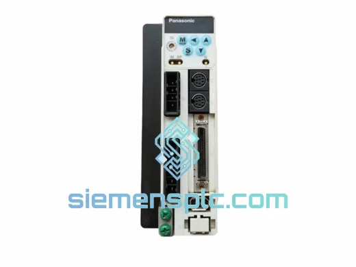
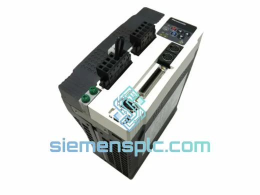
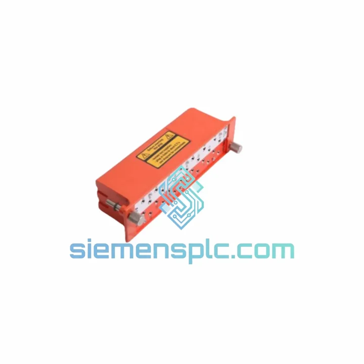
Panasonic MDDDT3530 AC Servo Drive
c MDDDT3530 MINAS A4 Series
Origin Japan
AC Servo Drive
Request verified availability, condition, replacement risk review, packing options and courier lead time for 581B740C.
Click Request Quote and the part number is inserted into the inquiry form automatically.
Core fields for model confirmation and RFQ routing. Detailed product narrative remains below.
The Panasonic 581B740C is a purpose-engineered industrial PCB assembly deployed as the primary control and signal-processing substrate within Panasonic servo drive and factory automation platforms. Within a closed-loop motion control architecture, this board occupies the functional layer between the power stage and the command interface — receiving encoder feedback, executing current-loop compensation algorithms, and issuing PWM gate-drive signals to the IGBT bridge at deterministic cycle intervals. Its role is not peripheral; it is the computational and signal-routing backbone that determines whether a servo axis tracks its velocity and position reference with sub-millisecond fidelity or introduces latency that degrades throughput and product quality.
Industrial procurement teams and maintenance engineers sourcing the 581B740C require a supplier with verified stock, traceable origin documentation, and the technical depth to confirm compatibility before shipment. siemensplc.com maintains physical inventory of this component at our Xiamen, China facility, with export logistics configured for DHL Express, FedEx International Priority, and UPS Worldwide — covering delivery to North America, Europe, Southeast Asia, the Middle East, and Africa within 3–7 business days from order confirmation.
Real-time Stock & RFQ: [email protected] | WhatsApp: +86 18359268345
| Parameter | Specification |
|---|---|
| Manufacturer | Panasonic Corporation (Industrial Devices & Solutions) |
| Part Number / SKU | 581B740C |
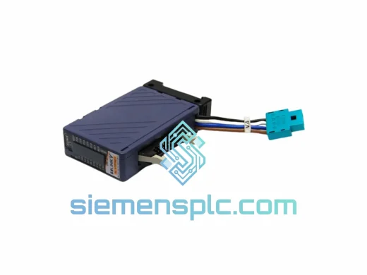
| Component Classification | Industrial PCB Assembly — Servo Drive Control Board |
| Primary Function | Signal processing, encoder feedback conditioning, PWM generation |
| Compatible Platform | Panasonic MINAS A-series servo amplifiers; FP-series PLC-integrated motion systems |
| Operating Temperature | 0°C to +55°C (storage: -20°C to +65°C) |
| Humidity Tolerance | 5% to 90% RH, non-condensing |
| PCB Layer Count | Multi-layer (≥6L, impedance-controlled traces for high-speed signal integrity) |
| Connector Interface | OEM-matched board-to-board and ribbon connectors; no field modification required |
| EMC Compliance | Designed to IEC 61800-3 Category C2 conducted/radiated emission limits |
| ESD Protection | TVS diode arrays on all external signal lines; handled per ANSI/ESD S20.20 |
| Unit Weight (packaged) | Approx. 4,460 g |
| Condition | New / Genuine OEM (surplus stock available; specify at inquiry) |
| Warranty | 12 months from date of shipment — siemensplc.com quality assurance |
| Origin | Japan (Panasonic OEM manufacture) |
The 581B740C operates within a layered hardware architecture where signal integrity and deterministic timing are non-negotiable. Several design characteristics distinguish this board from generic PCB assemblies:
Encoder Feedback Signal Conditioning: Incremental and absolute encoder signals entering the board pass through differential line receiver ICs (typically RS-422 compliant) before reaching the FPGA or DSP processing core. This differential topology rejects common-mode noise induced by adjacent motor cables carrying high dV/dt switching transients — a critical requirement in servo cabinets where signal cables and power cables share conduit runs. The receiver threshold hysteresis prevents false edge detection at low signal amplitudes, maintaining position count integrity even under conducted interference conditions.
PWM Generation and Dead-Time Insertion: The board’s gate-drive signal chain incorporates hardware dead-time insertion logic — a fixed blanking interval (typically 2–4 µs) enforced between the turn-off of one IGBT and the turn-on of its complementary device in the same half-bridge leg. This is implemented in dedicated gate-drive ICs rather than in firmware, ensuring the dead-time is immune to software latency or interrupt jitter. The consequence is reliable shoot-through prevention across the full operating temperature range without relying on processor cycle accuracy.
EMC Design — Conducted Emission Suppression: Power supply rails entering the board are filtered through multi-stage LC networks with X/Y-class capacitors referenced to the chassis ground plane. The PCB ground plane is segmented to isolate the analog signal ground (encoder, resolver, analog command inputs) from the digital switching ground, with a single-point star connection at the DSP reference node. This topology prevents high-frequency switching currents from the gate-drive section from coupling into the analog measurement paths, which would manifest as velocity ripple or position noise in the closed-loop response.
Thermal Management Architecture: High-dissipation components — gate-drive ICs, linear regulators, and DSP cores — are positioned over internal copper pour areas that conduct heat laterally to the board edge, where the servo amplifier chassis provides a thermal interface. Component placement follows a thermal gradient strategy: heat-sensitive analog components are located away from switching nodes, and thermal vias are used beneath power packages to reduce junction-to-board thermal resistance.
Every 581B740C unit dispatched from siemensplc.com’s Xiamen facility undergoes a structured pre-shipment verification sequence. Visual inspection confirms PCB surface condition, component seating, solder joint integrity, and label authenticity against Panasonic OEM reference samples. Units sourced from verified distribution channels are accompanied by traceability documentation linking the unit to its original manufacturer batch. ESD-sensitive handling is maintained throughout — boards are stored in anti-static bags within humidity-controlled racking and packed in conductive foam-lined cartons for transit.
Export documentation provided with each shipment includes a commercial invoice, detailed packing list, certificate of origin (China), and — upon request — a material safety data sheet and RoHS compliance declaration. Customs HS code classification is pre-assigned to minimize clearance delays at destination ports.
Logistics partners include DHL Express (standard for single-unit and small-quantity orders), FedEx International Priority, UPS Worldwide Express, and sea freight consolidation for bulk procurement. Typical transit times: 3–5 business days to Europe and North America via express courier; 5–10 business days to Southeast Asia, Middle East, and South America. In-stock units ship within 1 business day of payment confirmation. A tracking number is issued at the time of dispatch and shared via email.
The 12-month warranty covers manufacturing defects and functional failure under normal operating conditions. Warranty claims are processed with a replacement-first policy — a replacement unit ships before the defective unit is returned, minimizing production downtime for the customer.
Email: [email protected]
WhatsApp: +86 18359268345
Web: siemensplc.com
Location: Xiamen, China
© 2026 siemensplc.com. All rights reserved.
We check the full part number, brand, series and visible nameplate information before quotation.
Sales confirms stock path, condition option, quantity and realistic lead time for export dispatch.
DHL, FedEx, UPS or buyer courier arrangements can be reviewed with packing requirements.
Similar brand or category products for fast comparison and multi-item RFQ lists.