Siemens
RFQ Ready
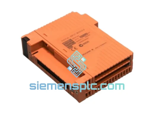
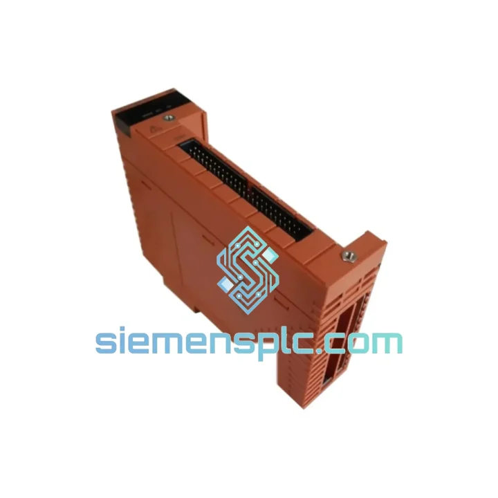
Siemens A5E00097681 I/O Module – SIMATIC ET 200
SIMATIC S7 Series
Origin DE
I/O Module
Request verified availability, condition, replacement risk review, packing options and courier lead time for SDV144-S13-S4.
Click Request Quote and the part number is inserted into the inquiry form automatically.
Core fields for model confirmation and RFQ routing. Detailed product narrative remains below.
The Siemens SDV144-S13-S4 is a 16-channel transistor digital output module engineered for deployment within SIMATIC S7-series programmable logic controller architectures. Its primary function is to translate binary control signals from the CPU’s process image output table into discrete 24 VDC switching commands at the field device level — actuating solenoid valves, motor contactors, indicator lamps, and relay coils with sub-millisecond propagation latency. The module occupies a single slot on the S7 backplane and communicates via the internal P-bus, sustaining a cycle-synchronous data exchange that eliminates output jitter under high-frequency scan conditions.
Designed for continuous-duty industrial environments, the SDV144-S13-S4 integrates optocoupler-based galvanic isolation on each output channel, providing a minimum 500 VAC isolation barrier between the logic-side circuitry and the field-side load circuit. This architecture prevents ground loop interference and protects the CPU backplane from transient overvoltage events originating at inductive field loads. Each channel incorporates an internal freewheeling diode clamp rated for inductive load suppression, reducing the need for external surge protection components in standard solenoid valve wiring configurations.
Real-time Stock & RFQ: [email protected] | WhatsApp: +86 18359268345
| Parameter | Specification |
|---|---|
| Part Number / SKU | SDV144-S13-S4 |
| Manufacturer | Siemens AG |
| Product Family | SIMATIC S7 Series |
| Module Function | Digital Output (DO) |
| Number of Output Channels | 16 |
| Output Signal Type | 24 VDC transistor (sourcing PNP) |
| Rated Load Voltage | 24 VDC (20.4 – 28.8 VDC operating range) |
| Maximum Output Current per Channel | 0.5 A |
| Total Module Load Current | 4 A (sum of all channels) |
| Short-Circuit Protection | Electronic, per channel, auto-reset |
| Galvanic Isolation | 500 VAC optocoupler isolation, logic vs. field |
| Backplane Interface | SIMATIC S7 P-bus (parallel backplane bus) |
| Propagation Delay (ON) | ≤ 0.5 ms |
| Propagation Delay (OFF) | ≤ 1.0 ms |
| Operating Temperature | 0°C to +60°C (horizontal mounting) |
| Storage Temperature | -40°C to +70°C |
| Relative Humidity | 10% to 95%, non-condensing |
| Degree of Protection | IP20 (EN 60529) |
| Vibration Resistance | 10–58 Hz: 0.075 mm amplitude; 58–150 Hz: 1 g |
| Shock Resistance | 15 g / 11 ms (IEC 60068-2-27) |
| EMC Immunity | EN 61000-4-2 (ESD), EN 61000-4-4 (EFT/Burst), EN 61000-4-5 (Surge) |
| Power Consumption (backplane) | ≤ 80 mA at 5 VDC |
| Dimensions (W × H × D) | 40 mm × 125 mm × 120 mm |
| Weight | Approx. 200 g |
| Mounting | S7-300 DIN rail profile rack |
| Certifications | CE, UL, cUL, ATEX Zone 2 (Ex nA), IECEx |
| Warranty | 12 months from date of shipment |
Optocoupler Isolation Architecture: Each of the 16 output channels is driven through a dedicated high-speed optocoupler with a typical current transfer ratio (CTR) of 100–300% at 10 mA forward current. The LED driver stage on the logic side is powered from the 5 VDC backplane rail, while the phototransistor output stage draws from the 24 VDC field supply. This hard separation means that a field-side wiring fault — including a dead short to ground — cannot propagate a destructive voltage spike back through the P-bus into the CPU module. The isolation capacitance between primary and secondary is held below 10 pF, which limits high-frequency common-mode noise coupling to negligible levels even in environments with aggressive variable-frequency drive (VFD) installations nearby.
Electronic Short-Circuit Protection: Each channel incorporates a current-limiting MOSFET driver with an integrated thermal shutdown circuit. When output current exceeds the 0.5 A per-channel threshold — typically caused by a wiring short or a failed actuator coil — the driver enters a current-fold-back mode, reducing output current to approximately 50 mA while asserting a diagnostic fault bit in the module’s status register. The CPU reads this fault bit within the next scan cycle and can execute a programmed response (alarm, interlock, or graceful shutdown) without requiring manual intervention. The protection circuit resets automatically once the fault condition is cleared, eliminating the need for manual fuse replacement.
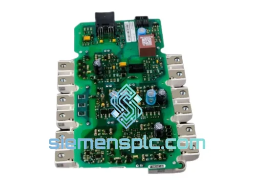
EMC Design and Conducted Emission Suppression: The module’s PCB layout employs a four-layer stackup with dedicated ground planes separating the logic and field power domains. Ferrite bead filters are placed on the 24 VDC field supply input traces to attenuate conducted emissions in the 1–30 MHz range. The front connector wiring interface includes internal RC snubber networks on each output pin, suppressing the high-frequency transients generated by inductive load switching. These design choices allow the SDV144-S13-S4 to maintain compliance with EN 55011 Class A emission limits without requiring additional external filtering in standard panel installations.
Backplane P-Bus Timing and Scan Synchronization: The module’s internal ASIC latches output data from the P-bus during the CPU’s output phase, holding the latch state stable throughout the remainder of the scan cycle. This prevents partial output updates — a condition that can occur in modules using asynchronous bus interfaces — and ensures that all 16 channels switch simultaneously at the end of each CPU output phase. For applications requiring deterministic output timing, this synchronous latch architecture eliminates the channel-to-channel skew that would otherwise accumulate in multi-module output configurations.
Every Siemens SDV144-S13-S4 unit supplied by siemensplc.com is sourced through verified Siemens-authorized distribution channels. Each module carries the original Siemens factory label with a traceable serial number and date code. Before dispatch, our technical team performs a power-on functional verification: the module is seated in a test rack, addressed by a STEP 7 hardware configuration, and each output channel is exercised through a full ON/OFF switching cycle under a resistive test load. Channel diagnostic status is confirmed fault-free before the unit is cleared for shipment.
Shipments originate from our warehouse in Xiamen, China, with access to DHL Express, FedEx International Priority, and UPS Worldwide Expedited services. Standard in-stock orders are dispatched within 1–2 business days. Export documentation — including commercial invoice, packing list, certificate of conformance, and HS code declaration (HS 8537.10) — is prepared for every shipment to facilitate smooth customs clearance in the destination country. We have active shipping lanes to the EU, Middle East, Southeast Asia, North America, and Australia, with typical transit times of 3–7 business days via express courier.
All units are shipped in anti-static packaging with foam cushioning inserts rated for the module’s vibration and shock specifications. A 12-month warranty covers manufacturing defects and functional failures under normal operating conditions. Warranty claims are processed with a replacement-first policy: a verified replacement unit is dispatched before the defective unit is returned, minimizing production downtime for our customers.
📧 Email: [email protected]
📱 WhatsApp: +86 18359268345
🌐 Web: siemensplc.com
📍 Location: Xiamen, China
© 2026 siemensplc.com. All rights reserved.
We check the full part number, brand, series and visible nameplate information before quotation.
Sales confirms stock path, condition option, quantity and realistic lead time for export dispatch.
DHL, FedEx, UPS or buyer courier arrangements can be reviewed with packing requirements.
Similar brand or category products for fast comparison and multi-item RFQ lists.