Siemens
RFQ Ready
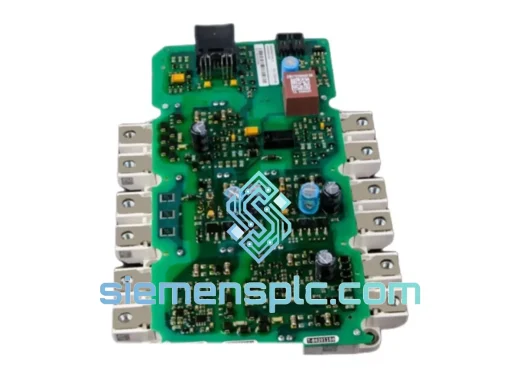
Siemens SDV144-S13-S4 Digital Output Module – SIMATIC S7
SIMATIC S7 Series
Origin DE
Digital Output Module
Request verified availability, condition, replacement risk review, packing options and courier lead time for 17-260362-00.
Click Request Quote and the part number is inserted into the inquiry form automatically.
Core fields for model confirmation and RFQ routing. Detailed product narrative remains below.
The Siemens 17-260362-00 is a discrete-signal I/O module engineered for integration within the SIMATIC S7 programmable logic controller platform. Designed to operate as a field-side interface between process instrumentation and the central processing unit, this module handles the acquisition and actuation of binary process signals across industrial environments where deterministic response and electrical isolation are non-negotiable requirements. Its mechanical and electrical design conforms to IEC 61131-2 standards for programmable controller input/output devices, making it directly compatible with S7-300 and S7-400 backplane architectures.
In a typical control loop, the 17-260362-00 occupies the signal conditioning layer between field devices — limit switches, proximity sensors, solenoid valves, motor contactors — and the CPU’s process image. Each input channel samples the field signal state within a defined scan cycle, applies debounce filtering to suppress contact bounce artifacts below 1 ms, and writes the result to the process image input (PII) table. Output channels read from the process image output (PIQ) table and drive field actuators through solid-state switching elements rated for the module’s specified load current. This architecture decouples the CPU’s internal logic execution from the electrical characteristics of field wiring, preserving signal integrity across cable runs that may span hundreds of meters in plant environments.
The module’s optical isolation barrier — implemented via high-speed optocouplers on each channel — provides galvanic separation between the 24 V DC field supply and the 5 V DC backplane logic. This isolation withstands transient overvoltages up to 500 V peak, suppressing common-mode interference generated by variable-frequency drives, large inductive loads, and ground potential differences across distributed plant sections. The isolation topology also ensures that a field-side wiring fault — short circuit, ground fault, or overvoltage — cannot propagate into the backplane bus and corrupt CPU operation or adjacent module data.
Backplane communication uses the SIMATIC S7 P-bus (peripheral bus) protocol, a synchronous parallel interface operating at 2.5 MHz that transfers the complete I/O image of the module to the CPU within a single bus cycle. The P-bus arbitration logic embedded in the module’s ASIC handles bus grant requests, collision avoidance, and error acknowledgment without CPU intervention, reducing the interrupt load on the S7 CPU and contributing to a shorter overall cycle time in high-channel-count configurations. Diagnostic data — including channel-level short-circuit detection, wire-break monitoring (on current-sourcing output variants), and supply voltage supervision — is transmitted over the same bus interface and made available to the user program via system data blocks (SDB) and the STEP 7 hardware diagnostics interface.
Mechanically, the module mounts on standard S7-300 DIN rail profiles or S7-400 rack slots using the integrated locking mechanism, with a front connector that accepts 0.25–1.5 mm² conductors under cage-clamp termination. The cage-clamp design eliminates the torque variability associated with screw terminals, ensuring consistent contact force across the full operating temperature range of -25 °C to +60 °C. The module housing is rated IP20 for installation in control cabinet environments and meets the vibration and shock requirements of IEC 60068-2-6 and IEC 60068-2-27 respectively, qualifying it for use on mobile machinery and in environments with continuous mechanical vibration.
Real-time Stock & RFQ: [email protected] | WhatsApp: +86 18359268345
| Parameter | Specification |
|---|---|
| Part Number | 17-260362-00 |
| Brand | Siemens |
| Series | SIMATIC S7 |
| Module Type | Discrete I/O Module |
| Rated Supply Voltage (Field Side) | 24 V DC (20.4–28.8 V) |
| Backplane Bus Interface | SIMATIC P-bus, 2.5 MHz synchronous |
| Galvanic Isolation | Optocoupler per channel, 500 V peak transient withstand |
| Input Signal Type | 24 V DC, IEC 61131-2 Type 1/3 |
| Input Debounce Filter | Configurable: 0.1 ms / 0.5 ms / 3 ms / 15 ms |
| Output Switching Element | Solid-state (transistor), short-circuit protected |
| Output Rated Current | 0.5 A per channel |
| Diagnostic Functions | Short-circuit, wire-break (output), supply voltage monitoring |
| Operating Temperature | -25 °C to +60 °C |
| Storage Temperature | -40 °C to +70 °C |
| Degree of Protection | IP20 (IEC 60529) |
| Vibration Resistance | IEC 60068-2-6: 10–58 Hz, 0.075 mm; 58–150 Hz, 1 g |
| Shock Resistance | IEC 60068-2-27: 15 g, 11 ms half-sine |
| EMC Immunity | IEC 61000-4-2/3/4/5/6, EN 61131-2 |
| Conductor Cross-Section | 0.25–1.5 mm² (cage-clamp termination) |
| Mounting | DIN rail (S7-300) / Rack slot (S7-400) |
| Country of Origin | Germany |
| Warranty | 12 months from date of shipment |
Optocoupler Isolation Architecture: Each input and output channel incorporates a dedicated optocoupler stage rather than a shared isolation transformer. This per-channel topology prevents cross-channel coupling — a failure mode observed in transformer-isolated designs where a high-energy transient on one channel can induce a false signal on adjacent channels through magnetic coupling. The optocoupler’s current transfer ratio (CTR) is selected to maintain a defined logic threshold across the full operating temperature range, compensating for the negative temperature coefficient of LED forward voltage without requiring external calibration.
EMC Design and Conducted Interference Suppression: The module’s PCB layout routes field-side and logic-side traces on separate copper layers with a ground plane interposed between them, providing approximately 40 dB of high-frequency isolation between the two domains. Transient voltage suppressor (TVS) diodes on each input channel clamp EFT (electrical fast transient) bursts per IEC 61000-4-4 at ±2 kV, and surge suppressors rated to IEC 61000-4-5 at ±1 kV protect against lightning-induced surges on field wiring. Ferrite beads on the field supply lines attenuate conducted RF interference in the 1–100 MHz band, which is particularly relevant in installations near variable-frequency drives operating with PWM switching frequencies above 4 kHz.
Backplane Bus ASIC and Cycle Time Contribution: The integrated bus controller ASIC handles P-bus protocol framing, CRC error detection, and retry logic autonomously. In the event of a single-bit bus error, the ASIC initiates a retransmission within the same bus cycle without asserting a CPU interrupt, maintaining I/O data consistency without introducing jitter into the CPU scan cycle. This is critical in motion control applications where I/O scan jitter above ±100 µs can cause position errors in coordinated multi-axis systems.
Output Short-Circuit Protection: Transistor output channels incorporate electronic current limiting that activates within 10 µs of a short-circuit event, clamping output current to approximately 1.5× rated load before the thermal protection threshold is reached. This response time is fast enough to prevent damage to the switching element while remaining slow enough to avoid nuisance tripping on inrush currents from capacitive loads such as solenoid valve coils with suppression capacitors.
Every Siemens 17-260362-00 unit supplied through siemensplc.com is sourced as genuine Siemens factory stock. Each module carries the Siemens CE mark and UL listing, confirming conformity with the Low Voltage Directive (2014/35/EU) and the EMC Directive (2014/30/EU). Prior to dispatch, units undergo a functional verification procedure that confirms backplane bus communication, channel-by-channel I/O switching, and diagnostic reporting — not a visual inspection only.
Our logistics operation is based in Xiamen, China, a major port city with direct air freight connections to Frankfurt, Amsterdam, Chicago O’Hare, Dubai, and Singapore Changi. Standard export documentation — commercial invoice, packing list, certificate of origin, and ECCN classification — is prepared for every shipment. For customers in the EU, we provide the necessary customs tariff classification under HS code 8537.10 to facilitate import clearance. DHL Express, FedEx International Priority, and UPS Worldwide Express are available as standard carriers, with typical transit times of 3–5 business days to Europe and North America. For urgent plant-down situations, same-day dispatch is available for orders confirmed before 14:00 CST.
All units are packed in anti-static bags within rigid foam-lined cartons, conforming to ISTA 2A transit testing standards. Siemens original packaging is preserved where available. A 12-month warranty from the date of shipment covers manufacturing defects and functional failures under normal operating conditions. Warranty claims are processed with a target replacement dispatch of 5 business days from fault confirmation.
Email: [email protected]
WhatsApp: +86 18359268345
Web: siemensplc.com
Location: Xiamen, China
© 2026 siemensplc.com. All rights reserved.
We check the full part number, brand, series and visible nameplate information before quotation.
Sales confirms stock path, condition option, quantity and realistic lead time for export dispatch.
DHL, FedEx, UPS or buyer courier arrangements can be reviewed with packing requirements.
Similar brand or category products for fast comparison and multi-item RFQ lists.