Product Overview
10030-05-30-05-02 — Same-Day Dispatch. Every Hour of Downtime Has a Price Tag.
A failed proximity probe on a critical rotating machine is not a maintenance event — it is a production emergency. Whether you are protecting a steam turbine, a centrifugal compressor, or a boiler feed pump, the Bently Nevada 10030-05-30-05-02 is the field-replaceable unit standing between your machine and an unplanned trip. When the driver output drops out of range and the 3500 rack throws a NOT OK, you do not have time to wait three weeks for a factory order.
We carry verified stock of the 10030-05-30-05-02 at our Xiamen warehouse. Orders confirmed before 15:00 CST ship the same business day via DHL Express or FedEx International Priority. No backorder promises. No “subject to availability” disclaimers. The unit is on the shelf, inspected, and ready to move.
URGENT REQUIREMENT? Contact: [email protected] | WhatsApp: +86 18359268345
Quick Technical Datasheet
| Parameter |
Specification |
| Part Number |
10030-05-30-05-02 |
| Manufacturer |
Bently Nevada (Baker Hughes) |
| Series |
3300 XL Proximity Transducer System |
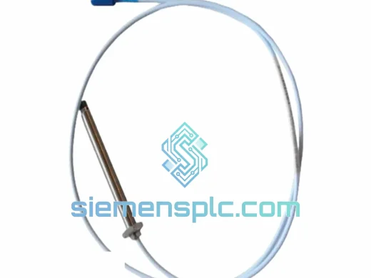
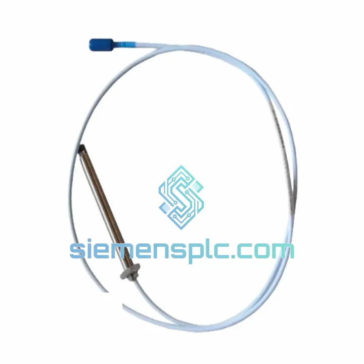
| Sensing Technology |
Eddy-Current, Non-Contact |
| Probe Tip Diameter |
5 mm |
| Integral Cable Length |
5 m, armored coaxial |
| Linear Measurement Range |
0.25 mm – 2.25 mm (10–90 mil) |
| Nominal Sensitivity |
7.87 V/mm (200 mV/mil) |
| Supply Voltage |
−24 VDC (via matched 3300 XL driver) |
| Operating Temperature |
−35 °C to +177 °C |
| Target Material |
AISI 4140 steel or equivalent ferromagnetic alloy |
| Probe Body Material |
316 Stainless Steel |
| Sensing Face Material |
PEEK polymer |
| Compliance |
CE, RoHS compatible |
| Compatible Driver |
Bently Nevada 330180-series (3300 XL 8 mm driver) |
| Compatible Extension Cable |
330130-series (length must match system calibration) |
| Stock Status |
✔ Ready to Ship — Xiamen Warehouse |
| Dispatch Lead Time |
Same business day (orders before 15:00 CST) |
Troubleshooting & Replacement Tips
Ten years of field calls on rotating machinery protection systems produce a short list of patterns. Here is what actually goes wrong with the 10030-05-30-05-02 and how to replace it without creating a second fault.
Failure Patterns You Will Recognize
-
Driver output outside −10 V to −18 V at nominal gap: Before condemning the probe, measure DC output at the driver terminal strip with a calibrated meter. A cracked PEEK tip, a cable break at the armor termination near the probe body, or a corroded connector center pin will all produce this symptom. The driver is rarely the cause when the probe has been in service more than two years.
-
Intermittent OK/NOT OK relay chatter on the 3500 monitor: Flex the armored cable along its full length while watching the driver output on a meter. If the voltage jumps during flexing, the fault is a micro-fracture in the coaxial cable — almost always within 150 mm of the probe body where the cable exits the armor. This is a cable-and-probe assembly failure, not a monitor or driver fault. Replace the full 10030-05-30-05-02 assembly.
-
Elevated 1× vibration reading immediately after probe swap: The slow-roll vector was not reset. The 3500 monitor stores a runout compensation vector that is specific to the original probe’s gap and position. After any probe replacement, you must perform a slow-roll vector subtraction reset in Bently Nevada System 1 or directly in the 3500 rack. Skipping this step produces a false vibration baseline that will chase you through the next outage.
-
Driver NOT OK LED on immediately after installation: The gap is wrong. For a 5 mm probe, the linear midpoint is 1.0–1.25 mm (40–50 mil). Use a calibrated feeler gauge — do not estimate by feel. A gap set outside the linear range drives the driver into NOT OK regardless of probe condition. This accounts for roughly 30% of “defective probe” returns we see from the field.
-
3500 rack showing “Transducer Not OK” after power-up: Some 3500 firmware versions latch the NOT OK state in hardware. A soft reset from the front panel does not clear it. Cycle power to the I/O module in the affected rack slot. If the fault persists after power cycling with a known-good probe installed at correct gap, the driver module itself requires evaluation.
Replacement Procedure — Field Reference
- Notify the control room. Obtain a hot-work or confined-space permit as applicable. Confirm whether the machine can remain online — most 3500 installations allow channel bypass for probe swap without a machine trip.
- Bypass the affected channel in the 3500 monitor to suppress spurious trip signals during removal and installation.
- Disconnect the extension cable at the junction box. Never pull from the probe body or the cable armor — always disconnect at the nearest junction point.
- Unthread the probe from the mounting bracket. Count the turns as you remove it so the replacement goes in at the same thread engagement depth as a starting point for gap adjustment.
- Install the new 10030-05-30-05-02. Thread in to the same depth, then fine-adjust gap to 1.0–1.25 mm using a feeler gauge. Torque the jam nut to the value specified in the Bently Nevada installation drawing for your bracket material — typically 14–20 N·m. Do not over-torque; the stainless threads in aluminum brackets strip easily.
- Reconnect the extension cable. Verify the locking ring is fully seated — a half-turn short on the connector is enough to produce intermittent output.
- Measure driver output at the terminal strip. Confirm −10 V to −18 V DC at the installed gap before removing the channel bypass.
- Remove the channel bypass in the 3500 monitor. The OK relay should close within 2 seconds. If it does not, recheck gap before assuming a probe fault.
- Reset the slow-roll vector in System 1 or the 3500 rack to re-establish the vibration baseline for this channel.
- Log the replacement: new probe serial number, installed gap measurement, driver output voltage, and date. This record is essential for the next outage planning cycle.
Configuration Checks Before You Close Out
- The 10030-05-30-05-02 is a probe-only assembly. It requires a matched 330130-series extension cable and a 330180-series 3300 XL driver. Do not mix cable lengths between probe and driver without recalibrating the complete transducer system — sensitivity shifts with cable length.
- In the 3500 Rack Configuration Software (RCS), verify the channel sensitivity setting still reads 200 mV/mil after the swap. A configuration file mismatch produces scaled vibration errors that are difficult to trace without the RCS open in front of you.
- For ATEX/IECEx hazardous area installations: confirm the replacement probe carries the same Ex certification as the original. The standard 10030-05-30-05-02 variant is not intrinsically safe. Verify your zone classification before installation and before ordering.
Reliability in Harsh Conditions
The 3300 XL probe body is machined from 316 stainless steel with a PEEK sensing face. That combination is not accidental — it was chosen because it survives the specific abuse that rotating machinery environments deliver: oil mist, steam condensate, aggressive cleaning solvents, and the mechanical shock of compressor surge events. The armored coaxial cable uses a stainless braid over PTFE dielectric. PTFE does not absorb moisture and does not stiffen at low temperatures, which matters when you are commissioning a machine in a cold climate or after a winter shutdown.
Vibration fatigue is the primary failure mechanism for any wired sensor mounted near a rotating machine. The 10030-05-30-05-02 cable-to-body termination is potted and strain-relieved at the factory. This is the joint that fails first on cheaper aftermarket probes — typically within 6 to 12 months of installation in high-vibration applications. The OEM potting compound maintains its bond through the thermal cycling that bearing housings experience between cold start and full operating load.
Temperature range matters more than the datasheet number suggests. A steam turbine bearing housing can swing from 10 °C at cold start to 160 °C at full load within two hours. The probe’s rated range of −35 °C to +177 °C reflects actual qualification testing, not a calculated estimate. Units in our Xiamen warehouse are stored in climate-controlled conditions — 18 to 25 °C, relative humidity below 60% — to preserve connector integrity and cable flexibility before shipment. Connectors that have been stored in humid, uncontrolled conditions develop oxidation on the center pin that produces intermittent output from the first day of installation.
Our pre-shipment inspection covers connector condition, cable armor integrity, and probe tip surface. Any unit showing connector oxidation, armor damage, or tip surface irregularity is quarantined. It does not ship. When you install the replacement, apply a thin film of dielectric grease to the connector mating surfaces before assembly. This single step eliminates the majority of intermittent connector faults reported in the first 90 days after installation.
Global Express Logistics
Our dispatch hub is in Xiamen, Fujian Province — a primary export gateway with direct DHL and FedEx collection. Here is how an urgent order moves from our warehouse to your site:
-
Order confirmation (Day 0): You confirm the order and provide the delivery address plus any required customs documentation — commercial invoice format, HS code declaration, end-user statement if your country requires one. We generate the shipping label and pull the unit from bonded stock immediately.
-
Same-day dispatch (Day 0, cutoff 17:00 CST): The unit is packed in anti-static foam inside a double-wall export carton, labeled with the part number and your purchase reference, and handed to DHL or FedEx for collection. Tracking number is sent to you within two hours of dispatch.
-
Export customs clearance (Day 0–1): We pre-file export documentation from the China side. For most destinations, the shipment clears Chinese export customs within 4–8 hours of carrier pickup. We provide commercial invoice, packing list, and certificate of origin in the formats required by your country’s import authority.
-
In-country delivery (Day 2–5 by destination): DHL Express delivers to major industrial hubs in Southeast Asia in 2–3 days, the Middle East in 3–4 days, and Europe in 4–5 days. Remote or island sites may add one day for last-mile delivery.
-
Project and bulk orders: For five or more units, we consolidate into a single shipment with a combined commercial invoice to simplify your import process. Sea freight via Xiamen Port is available for non-urgent bulk orders — typical transit 18–25 days to major destination ports.
-
Special import requirements: If your site requires fumigation certificates, SASO, SONCAP, or other destination-country certifications, contact us before placing the order. We will confirm what documentation we can provide before you commit.
Contact Information
Email: [email protected]
WhatsApp: +86 18359268345
Web: siemensplc.com
© 2026 siemensplc.com. All rights reserved.