ABB
In Stock OK
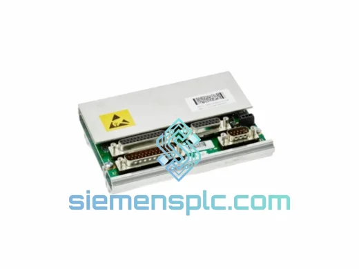
ABB SAFT125CHC Chopper Control Board – SAFT Series
Request verified availability, condition, replacement risk review, packing options and courier lead time for SAFT 125 CHC SAFT125CHC.
BrandABB
Part NumberSAFT 125 CHC SAFT125CHC
ConditionAvailability Check
Lead TimeRFQ Confirmation
DocumentsDatasheet / photos by RFQ
ShippingExport packing available
Auto-filled RFQ
SAFT 125 CHC SAFT125CHC
Click Request Quote and the part number is inserted into the inquiry form automatically.
- Reply by email: [email protected]
- WhatsApp / Tel: +86 18359268345
- Mon-Sat 9:00-18:00 GMT+8
Procurement Data
Key Product Information
Core fields for model confirmation and RFQ routing. Detailed product narrative remains below.
- Brand
- ABB
- Primary Part Number
- SAFT 125 CHC SAFT125CHC
- Product Type
- Chopper Control Board
- Product Family
- Other series
- Manufacturer
- ABB Ltd.
- Country of Origin
- SE
- Catalog Category
- Industrial Automation Spares
- Warranty
- 12 months from dispatch date
Model confirmed for inquiry
SAFT 125 CHC SAFT125CHC
Send quantity, destination and urgency. The RFQ form keeps this part number attached.
Request Quote
Product Overview
ABB SAFT125CHC Chopper Control Board – DC Braking Drive Module: Gate Drive Architecture and Control Loop Role
The ABB SAFT125CHC is the dedicated braking chopper control board within the ABB SAFT-series DC drive platform. Its function is singular and non-negotiable: it governs the switching of the braking chopper IGBT (or thyristor, depending on cabinet revision), clamping DC bus overvoltage during regenerative deceleration events. Without a correctly functioning SAFT125CHC, the drive’s DC bus is exposed to uncontrolled voltage rise during high-inertia load deceleration — a condition that leads to DC bus capacitor failure, IGBT destruction, and unplanned plant shutdown.
In the control loop hierarchy of an ABB SAFT DC drive, the SAFT125CHC sits between the main control board (SAFT125CON) and the power semiconductor stack. It receives a switching command signal from the control board when the DC bus voltage exceeds the programmed threshold — typically 10–15% above nominal DC bus voltage — and translates that logic-level signal into a high-current, isolated gate pulse capable of driving the braking chopper IGBT directly. The board’s response latency and gate drive current capability are the two parameters that determine whether the chopper fires cleanly or introduces switching stress into the power stage.
Real-time Stock & RFQ: [email protected] | WhatsApp: +86 18359268345
Technical Parameters
| Part Number | SAFT125CHC (also referenced as SAFT 125 CHC) |
| Manufacturer | ABB Ltd. |
| Product Series | SAFT (DC Drive Control Board Series) |
| Board Function | Braking Chopper Gate Drive & DC Bus Overvoltage Control |
| Switching Device Compatibility | IGBT / Thyristor braking chopper (frame-dependent) |
| Gate Drive Output | Isolated high-current gate pulse; optocoupler-based signal isolation |
| DC Bus Monitoring | Continuous analog voltage sensing; threshold-triggered switching command |
| Compatible Drive Frames | ABB SAFT 125 series; cross-compatibility with SAFT 115 subject to revision verification |
| Operating Temperature | 0°C to +55°C (ambient, forced-air cooled cabinet) |
| Storage Temperature | -25°C to +70°C |
| Humidity | 5–95% RH, non-condensing |
| PCB Standard | IEC 61800-3 EMC compliance; CE-marked drive assembly compatible |
| Weight | Approx. 400 g |
| Condition | New OEM / Surplus New (specify at inquiry) |
| Lead Time | In-stock: 1–3 business days; sourced: 7–15 business days |
| Warranty | 12 months from dispatch date |
Hardware Logical Analysis
The SAFT125CHC’s hardware design reflects the engineering constraints of high-power DC drive environments, where the control board must operate reliably within a cabinet that generates significant conducted and radiated electromagnetic interference.
Optocoupler Isolation Architecture: The gate drive signal path uses high-speed optocouplers to create a galvanic isolation barrier between the low-voltage control logic (operating at 5–24 VDC) and the gate drive output stage, which interfaces directly with the IGBT gate terminal at voltages typically in the +15 V / -8 V bipolar gate drive range. This isolation prevents high-voltage transients on the power side — common during IGBT turn-off, where collector voltage slew rates can exceed 1 kV/µs — from coupling back into the control logic and causing spurious switching commands or microcontroller resets.
EMC Design and Conducted Noise Immunity: The PCB layout of the SAFT125CHC follows ABB’s internal EMC design rules for drive control boards: power and signal ground planes are separated, decoupling capacitors are placed at each IC power pin, and gate drive traces are kept short and low-inductance to minimize ringing at turn-on. Ferrite beads are used on signal lines crossing between isolation domains. These measures allow the board to maintain correct switching behavior even in the presence of the common-mode noise generated by PWM-modulated power stages in adjacent drive cabinets.
DC Bus Voltage Sensing and Threshold Logic: The board incorporates a resistive voltage divider network that scales the DC bus voltage down to a level compatible with the onboard comparator circuit. The comparator output drives the optocoupler input when bus voltage exceeds the set threshold. Hysteresis is built into the comparator circuit to prevent chattering — a condition where the chopper switches on and off rapidly near the threshold voltage, generating excessive heat in the braking resistor and mechanical stress in the IGBT. The hysteresis band is factory-set and matched to the SAFT 125 drive’s DC bus capacitance and braking resistor thermal rating.
Gate Drive Current Capability: The output stage of the SAFT125CHC is designed to source and sink sufficient gate charge to switch the braking chopper IGBT within the ABB-specified turn-on and turn-off time windows. Inadequate gate drive current — a common failure mode in counterfeit or degraded replacement boards — results in extended switching transitions, increased IGBT switching losses, and eventual IGBT thermal failure. The SAFT125CHC’s output stage maintains gate drive current within OEM specification across the full operating temperature range.
System Integration Benefits
- Deterministic DC Bus Clamping: The board’s comparator response time is consistent across operating temperature, ensuring the braking chopper fires within a predictable window after the DC bus threshold is crossed — critical for protecting bus capacitors in high-inertia deceleration cycles.
- Zero Firmware Dependency: The SAFT125CHC operates as a hardwired analog/logic circuit. Its braking function is not dependent on drive firmware state, meaning it provides overvoltage protection even during drive CPU faults or communication loss events.
- Direct Board Swap Compatibility: The board uses the same connector footprint and signal interface as the original SAFT 125 factory installation, eliminating the need for wiring modifications or parameter re-entry during replacement.
- Fault Isolation Transparency: The board’s discrete circuit architecture allows field engineers to diagnose failures at the component level using standard multimeter and oscilloscope techniques — no proprietary diagnostic tools required.
- Reduced IGBT Stress: Correct gate drive timing, as delivered by a genuine SAFT125CHC, keeps IGBT switching losses within the device’s safe operating area (SOA). This directly extends the service life of the braking chopper IGBT module — a component with a significantly higher replacement cost than the control board itself.
- Braking Resistor Thermal Protection: The hysteresis logic prevents chopper chattering, which is the primary cause of braking resistor overheating in DC drive systems. Stable switching reduces resistor thermal cycling and extends resistor service life.
- Compatibility with Redundant Drive Architectures: In dual-drive or master-follower SAFT configurations, the SAFT125CHC’s isolated gate drive ensures that braking chopper operation on one drive does not introduce noise into the control bus of the parallel drive.
- Spare Parts Inventory Efficiency: A single SAFT125CHC board covers the braking chopper control function across multiple SAFT 125 cabinet variants, simplifying spare parts inventory management for maintenance teams operating mixed SAFT-series fleets.
Quality Assurance & Global Logistics
Every SAFT125CHC supplied by siemensplc.com is sourced through verified industrial distribution channels with full traceability documentation. Boards are inspected upon receipt for physical integrity — PCB condition, connector pin alignment, component presence, and label authenticity — and re-inspected before dispatch. Units are shipped in anti-static ESD bags with foam cushioning inside rigid outer cartons to prevent transit damage.
Our warehouse and dispatch operations are based in Xiamen, China — a designated free trade zone and one of China’s primary international logistics hubs. Xiamen’s port and air cargo infrastructure provides direct access to DHL Express, FedEx International Priority, UPS Worldwide Express, and SF International services, with consolidated sea freight available for bulk orders. Typical transit times: Asia-Pacific 2–5 days; Europe 4–7 days; North America 5–9 days; Middle East and Africa 5–10 days. All shipments include commercial invoice, packing list, and HS code documentation for smooth customs clearance.
The 12-month warranty covers manufacturing defects and functional failure under normal operating conditions. Warranty claims are processed with a replacement-first policy — a replacement unit is dispatched upon receipt and inspection of the returned board, minimizing plant downtime during the warranty process. Multi-currency payment is supported: USD, EUR, CNY, and HKD via T/T bank transfer, PayPal, and major credit cards.
Contact Information
Email: [email protected]
WhatsApp: +86 18359268345
Web: siemensplc.com
Location: Xiamen, China
© 2026 siemensplc.com. All rights reserved.
Ready to quote
[email protected]
Send This Part Number to Sales
RFQ workflow
Quality workflow ->
Confirmation Process
01Model confirmation
We check the full part number, brand, series and visible nameplate information before quotation.
02Availability reply
Sales confirms stock path, condition option, quantity and realistic lead time for export dispatch.
03Packing & courier
DHL, FedEx, UPS or buyer courier arrangements can be reviewed with packing requirements.
Continue sourcing
Browse full catalog ->
Related Automation Parts
Similar brand or category products for fast comparison and multi-item RFQ lists.
ABB
RFQ Ready
ABB 3HAC9330-1 Robot Speed Reducer – IRB6640-205/2.7
lRB240046 RB460
Origin SE
Robot Speed Reducer
ABB
RFQ Ready
ABB YT204001-JJ Speed Measurement Board
Ready to Ship
Origin SE
Speed Measurement Board