ABB
In Stock OK
ABB DSDO115 57160001-NF Digital Output Module – Advant OCS S100
Request verified availability, condition, replacement risk review, packing options and courier lead time for 57160001-NF.
BrandABB
Part Number57160001-NF
ConditionAvailability Check
Lead TimeRFQ Confirmation
DocumentsDatasheet / photos by RFQ
ShippingExport packing available
Auto-filled RFQ
57160001-NF
Click Request Quote and the part number is inserted into the inquiry form automatically.
- Reply by email: [email protected]
- WhatsApp / Tel: +86 18359268345
- Mon-Sat 9:00-18:00 GMT+8
Procurement Data
Key Product Information
Core fields for model confirmation and RFQ routing. Detailed product narrative remains below.
- Brand
- ABB
- Primary Part Number
- 57160001-NF
- Product Type
- Digital Output Module
- Series / Family
- Advant
- Manufacturer
- ABB (Asea Brown Boveri)
- Country of Origin
- SE
- Catalog Category
- I/O Modules
- Operating Temp.
- 0 °C to +55 °C
- Warranty
- 12 months from confirmed dispatch date
Model confirmed for inquiry
57160001-NF
Send quantity, destination and urgency. The RFQ form keeps this part number attached.
Request Quote
Product Overview
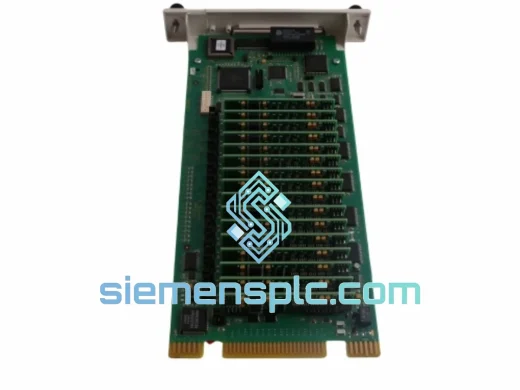
ABB DSDO115 57160001-NF: 16-Channel 24 V DC PNP Transistor Output Module for S100 I/O Bus Control Architectures
The ABB DSDO115 (57160001-NF) is a 16-channel sourcing transistor digital output module engineered for the ABB Advant OCS and MOD 300 distributed control system platforms. It occupies a single slot in the S100 I/O rack and interfaces directly with the S100 parallel backplane bus, receiving latched output commands from the Advant Controller CPU during each scan cycle’s output update phase. Each of the 16 channels drives a 24 V DC PNP transistor capable of sourcing up to 0.5 A continuously, making the module suitable for direct actuation of solenoid valves, motor starter auxiliary coils, pilot relays, and field indicator lamps without interposing relay stages.
In a process control loop, the DSDO115 represents the terminal discrete output node. Its position in the signal chain — between the deterministic CPU scan and the electrically hostile field environment — demands two properties that this module’s hardware architecture specifically addresses: galvanic isolation to prevent field-side fault energy from propagating onto the backplane, and per-channel fault containment to ensure that a single wiring fault does not cascade into a multi-channel output failure. Both properties are implemented in hardware, independent of firmware state, and remain active even during controller communication interruptions.
The module’s catalog suffix 57160001-NF identifies the specific hardware revision and regional compliance variant. In ABB’s S100 I/O family, the NF suffix designates the standard industrial temperature and humidity rating without conformal coating — the correct specification for climate-controlled control room enclosures operating within IEC 60068-2-1/2 standard conditions. Conformal-coated variants (suffix -CF) are specified for offshore or high-humidity environments; substituting an NF unit in a CF-specified application, or vice versa, constitutes a hardware configuration deviation that must be documented in the system’s safety case if the installation falls under IEC 61511 or IEC 62061 scope.
The DSDO115 has accumulated a substantial installed base across continuous-process industries: petroleum refining, ethylene and propylene production, chlor-alkali electrolysis, pulp and paper digestion, and combined-cycle power generation auxiliary systems. In these environments, DCS hardware is typically maintained on a corrective replacement basis rather than a scheduled lifecycle basis, which means the availability of revision-accurate spare modules — with a documented inspection history — directly determines the plant’s mean time to repair (MTTR) for discrete output faults. A verified DSDO115 57160001-NF in the maintenance inventory eliminates the lead-time risk associated with reactive sourcing of obsolete S100 I/O modules.
📦 Real-time Stock & RFQ: [email protected] | WhatsApp: +86 18359268345
Technical Parameters
| Parameter | Specification |
|---|---|
| Manufacturer | ABB (Asea Brown Boveri) |
| Catalog Number | DSDO115 / 57160001-NF |
| Module Class | 16-Channel Transistor Digital Output |
| Compatible Platforms | ABB Advant OCS, MOD 300 DCS |
| Backplane Bus | S100 Parallel I/O Bus |
| Output Topology | PNP Sourcing Transistor, per channel |
| Rated Field Supply Voltage | 24 V DC |
| Field Supply Operating Range | 20.4 – 27.6 V DC (±15%) |
| Max Load Current per Channel | 0.5 A continuous |
| Max Module Aggregate Current | 4.0 A (all 16 channels at full load) |
| Output Switching Response | ≤ 1 ms (ON transition and OFF transition) |
| Isolation Architecture | Per-channel optical coupler, logic-to-field galvanic separation |
| Short-Circuit Protection | Electronic current limiting, individual channel, non-latching |
| Fault Diagnostics | Per-channel status register, readable via S100 bus |
| Rack Form Factor | Single-slot S100 I/O rack card |
| Operating Temperature | 0 °C to +55 °C |
| Storage Temperature | −40 °C to +70 °C |
| Relative Humidity | 5% – 95% RH, non-condensing |
| Conformal Coating | None (NF variant; standard industrial enclosure rating) |
| Approximate Module Weight | 320 g |
| Country of Origin | Germany |
| Warranty Coverage | 12 months from confirmed dispatch date |
Hardware Logical Analysis
The DSDO115 implements a three-stage signal chain between the S100 backplane and the field terminal block, with each stage serving a distinct functional role in the module’s overall performance envelope.
Stage 1 — Latch Register and Bus Interface: During the CPU’s output update phase, the S100 bus controller executes a synchronous write cycle that deposits a 16-bit output word into the DSDO115’s on-card latch register. This register retains the commanded state between scan cycles using static CMOS latch cells powered from the backplane 5 V logic rail. The practical consequence is that field devices remain energized at their last commanded state throughout the entire scan period — including the logic execution and input acquisition phases — without any periodic refresh requirement. This eliminates the output flicker that would otherwise occur on inductive loads if the transistor drivers were driven directly from a time-multiplexed bus without intermediate latching.
Stage 2 — Per-Channel Optical Isolation: Each bit of the latch register drives the anode of a dedicated optical coupler LED. The LED side is referenced to the backplane 5 V logic common; the phototransistor collector side is referenced to the field 24 V DC supply common. This arrangement establishes a complete galvanic break between the two power domains at every channel. The isolation withstand voltage is rated to handle the common-mode transients generated by variable frequency drives, high-current contactors, and inductive load switching on the 24 V DC field rail — events that can produce transient voltages of several hundred volts peak on the field supply bus. Without this per-channel isolation, such transients would couple directly onto the S100 backplane through the output driver stage, potentially corrupting the latch register contents of adjacent modules or damaging the CPU’s bus interface circuitry.
Stage 3 — PNP Transistor Driver with Current Sensing: The phototransistor output of each optical coupler drives the base of a discrete PNP power transistor. An emitter-side current-sensing resistor monitors the channel load current in real time. When the sensed current exceeds the 0.5 A threshold — indicating a short-circuit condition or an overloaded field device — the driver enters a linear current-limiting mode. Critically, this is not a hard latch-off: the output remains active in a current-limited state, the fault current is bounded to a safe level, and the channel’s status register bit is set to indicate the fault condition. The DCS operator workstation can therefore display a differentiated alarm — “DO Channel 7: Overcurrent” — rather than a generic output failure, enabling maintenance personnel to identify the specific field wiring fault without manual channel-by-channel testing.
EMC Design: The PCB layout enforces a split ground plane topology, with the digital logic ground plane and the field-side power ground plane separated by the optical coupler row. Multilayer ceramic bypass capacitors at the field supply entry point provide broadband conducted noise suppression across the 150 kHz – 30 MHz frequency range, addressing IEC 61000-4-4 fast transient burst immunity and IEC 61000-4-6 conducted RF immunity requirements without external filter components. The backplane edge connector uses gold-plated contacts to maintain low contact resistance over the module’s service life, preventing the connector oxidation that is a documented failure mode in high-humidity industrial environments.
System Integration Benefits
- Deterministic scan-synchronous output updates: All 16 channels are updated simultaneously at the conclusion of each CPU scan cycle’s output phase. There is no asynchronous output queue, no channel-by-channel sequential update, and no variable latency between logic execution and field actuation — a property that is essential for interlock and emergency shutdown applications where output timing relative to input events must be bounded and verifiable.
- Independent per-channel fault containment: A short-circuit or overload on any single channel activates that channel’s current limiter without affecting the operating state of the remaining 15 channels. Partial system functionality is preserved during fault diagnosis, allowing the process to continue operating on unaffected output channels while the faulted field circuit is isolated and repaired.
- Structured diagnostic register accessible at scan rate: The module’s per-channel fault status register is mapped into the S100 I/O address space and polled by the CPU at every scan cycle. Fault events are therefore available to the SCADA historian with timestamp resolution equal to the controller scan period — typically 100 ms or better — enabling precise fault timeline reconstruction for root-cause analysis and regulatory reporting.
- Zero-configuration slot addressing: The DSDO115 derives its I/O address from its physical rack slot position via the S100 bus backplane addressing scheme. No DIP switches, rotary address selectors, or jumper configurations are required. This eliminates a documented source of commissioning errors in multi-module installations and simplifies module replacement: a replacement unit installed in the correct slot is immediately recognized by the controller without any configuration change.
- High channel density per rack slot: 16 discrete output channels in a single rack slot reduces the number of occupied positions required for discrete output functions. In space-constrained control cabinets where rack slot availability limits system expansion, the DSDO115’s channel density directly increases the number of field points that can be accommodated within the existing hardware footprint.
- Wide field supply tolerance for long cable runs: The ±15% field supply operating range (20.4 – 27.6 V DC) accommodates the resistive voltage drop on field cable runs of 200 – 500 m between the control room and remote field junction boxes. This tolerance eliminates the need for field-side voltage boosters or cable upsizing in installations where cable routing constraints limit conductor cross-section.
- Passive thermal management, no forced-air dependency: The module’s power dissipation under full 16-channel load is within the natural convection thermal budget of a standard IEC 60068-2-1/2 rated industrial enclosure at 55 °C ambient. No forced-air cooling fans are required, removing fan bearing wear-out as a maintenance item and eliminating a potential single-point failure from the enclosure’s thermal management subsystem.
- Native ABB engineering tool integration: The DSDO115 is recognized by ABB Control Builder M and MOD 300 engineering workstation software without additional device drivers or configuration files. Online force commands, live channel status monitoring, and I/O configuration are available directly from the engineering environment, reducing commissioning time and enabling remote diagnostic sessions without physical access to the control cabinet.
- IEC 61511 hardware baseline compatibility: In safety-instrumented system applications where the Advant OCS or MOD 300 platform forms part of the SIS hardware, maintaining genuine, revision-matched modules is a prerequisite for IEC 61511 hardware configuration validation. The DSDO115 57160001-NF is the documented hardware baseline for installations specifying this module; substituting a different revision or a non-genuine unit requires a formal hardware change assessment and may trigger a partial SIL re-verification.
Quality Assurance & Global Logistics
Every ABB DSDO115 57160001-NF unit dispatched from our Xiamen, China facility passes a structured pre-shipment inspection protocol before packaging. The protocol consists of four sequential verification stages:
Authenticity Verification: Part number labels, PCB silkscreen markings, and date codes are cross-referenced against ABB’s official documentation database. Component population on the PCB is inspected under 10× magnification and compared against the known-good reference for the 57160001-NF revision. Units with label anomalies, non-standard component substitutions, or evidence of unauthorized rework are quarantined and not shipped.
Mechanical Inspection: The S100 backplane edge connector is inspected for pin straightness, contact surface condition, and absence of oxidation or contamination. Contact resistance is measured at representative pins using a four-wire milliohm meter; readings above 10 mΩ trigger connector cleaning or unit rejection. The PCB surface is examined for solder joint integrity, component seating, and absence of physical damage from prior installation or handling.
Functional Verification (Refurbished Units): Refurbished units are bench-tested using an S100 rack test fixture. The test sequence validates backplane bus communication, latch register write/read integrity across all 16 channels, optical coupler switching response, transistor driver output voltage and current, and short-circuit protection activation. Test records are retained on file and provided with the shipment documentation upon request.
Packaging and Documentation: Approved units are individually sealed in IEC 61340-5-1 compliant anti-static shielding bags, cushioned in closed-cell polyethylene foam inserts, and packed in double-wall corrugated cartons rated for international air freight handling. Each shipment includes a commercial invoice, packing list, certificate of origin, and inspection report. FORM E preferential origin documentation for ASEAN trade agreement destinations is available upon request.
Dispatch originates from Xiamen, China. Orders confirmed before 15:00 CST are processed for same-day dispatch. International transit via DHL Express and FedEx International Priority delivers to major industrial destinations in Southeast Asia, the Middle East, Europe, and North America within 2 – 4 business days. Bulk orders of 10 or more units qualify for LCL sea freight consolidation with 7 – 18 day transit times. All shipments carry full cargo insurance and end-to-end tracking with proactive exception notifications for customs or transit delays. A 12-month warranty applies from the confirmed dispatch date; DOA units are replaced within 5 business days at no charge.
Contact Information
📧 Email: [email protected]
💬 WhatsApp: +86 18359268345
🌐 Web: siemensplc.com
📍 Location: Xiamen, China
© 2026 siemensplc.com. All rights reserved.
Ready to quote
[email protected]
Send This Part Number to Sales
RFQ workflow
Quality workflow ->
Confirmation Process
01Model confirmation
We check the full part number, brand, series and visible nameplate information before quotation.
02Availability reply
Sales confirms stock path, condition option, quantity and realistic lead time for export dispatch.
03Packing & courier
DHL, FedEx, UPS or buyer courier arrangements can be reviewed with packing requirements.
Continue sourcing
Browse full catalog ->
Related Automation Parts
Similar brand or category products for fast comparison and multi-item RFQ lists.
ABB
RFQ Ready
ABB GJR5143200R0001 35EK91 Analog Output Module – AC31 Advant Series
Advant
Origin SE
Analog Output Module
ABB
RFQ Ready
ABB 07DI92 GJR5252400R4101 Digital Input Module
Advant
Origin SE
PLC Digital Input Module