ABB
In Stock OK
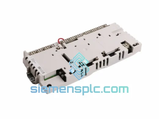
ABB 3BHB004661R0101 Gate Drive Interface Board – KUC711AE101 Series
Request verified availability, condition, replacement risk review, packing options and courier lead time for 3BHB004661R0101 KUC711AE101.
BrandABB
Part Number3BHB004661R0101 KUC711AE101
ConditionAvailability Check
Lead TimeRFQ Confirmation
DocumentsDatasheet / photos by RFQ
ShippingExport packing available
Auto-filled RFQ
3BHB004661R0101 KUC711AE101
Click Request Quote and the part number is inserted into the inquiry form automatically.
- Reply by email: [email protected]
- WhatsApp / Tel: +86 18359268345
- Mon-Sat 9:00-18:00 GMT+8
Procurement Data
Key Product Information
Core fields for model confirmation and RFQ routing. Detailed product narrative remains below.
- Brand
- ABB
- Primary Part Number
- 3BHB004661R0101 KUC711AE101
- Product Type
- Gate Drive Interface Board
- Series / Family
- S800
- Manufacturer
- ABB Group
- Country of Origin
- SE
- Catalog Category
- Motor Drives
- Warranty
- 12 months from date of dispatch
Model confirmed for inquiry
3BHB004661R0101 KUC711AE101
Send quantity, destination and urgency. The RFQ form keeps this part number attached.
Request Quote
Product Overview
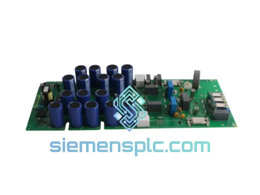
ABB 3BHB004661R0101 / KUC711AE101 — Fiber-Isolated IGBT Gate Drive Interface Board for ACS800, ACS880 & DCS800 Variable-Speed Drive Platforms
The ABB 3BHB004661R0101, carrying the functional board designation KUC711AE101, is the gate drive interface module that bridges the low-voltage control domain and the high-voltage IGBT power stack in ABB’s ACS800, ACS880, and DCS800 variable-speed drive families. Its position in the drive architecture is structurally critical: it receives switching commands from the RDCU or RINT control layer via ABB’s PPCS fiber-optic serial link, converts those commands into precisely timed gate pulses, enforces dead-time intervals in hardware, and executes device-level fault detection — all without delegating any of these functions to firmware task cycles or software protection loops. The board operates at the intersection of three independent engineering disciplines: high-speed galvanic isolation, deterministic commutation timing, and hardware-speed IGBT protection. Each of these functions is implemented in dedicated analog and digital gate drive circuitry on the PCB itself.
In a three-phase voltage-source inverter, the gate drive board manages six independent IGBT channels arranged as three half-bridge legs. Each leg requires a dead-time interval — a period during which both the upper and lower switch are simultaneously held off — to prevent cross-conduction that would create a direct short-circuit path across the DC bus. At DC bus voltages above 600 V and switching frequencies between 1 and 4 kHz, a missed or shortened dead-time event results in simultaneous conduction of both IGBTs in the affected leg, discharging the DC bus through the short-circuit path and driving junction temperatures beyond rated limits within microseconds. The 3BHB004661R0101 enforces dead-time intervals through hardware gate logic whose timing characteristics are determined by the physical parameters of the gate drive circuit — not by a software register, a firmware parameter, or a CPU peripheral configuration. Dead-time behavior is therefore a fixed electrical property of the board, invariant with respect to control board firmware version, CPU load, or PPCS communication latency.
Switching commands arrive at the 3BHB004661R0101 via ABB’s PPCS (Power Package Communication System) fiber-optic serial link — a proprietary high-speed protocol transmitted over plastic or glass optical fiber depending on the drive frame configuration. The fiber medium provides complete galvanic isolation between the control PCB and the gate drive board, and is inherently immune to the electromagnetic environment of the power stage. IGBT switching transitions in high-power drives generate dV/dt rates of 1 to 10 kV/µs across the DC bus, producing broadband conducted and radiated interference that propagates through the cabinet structure. Any copper signal path spanning the isolation boundary must contend with this interference through common-mode chokes, differential signaling, and shielded cabling. The 3BHB004661R0101 integrates the PPCS optical receiver and transmitter directly on the gate drive board, performing optical-to-electrical conversion at the power stage side of the isolation boundary. The result is a signal path with effectively infinite common-mode rejection across the full spectrum of IGBT switching harmonics, with no additional EMC mitigation hardware required between the control board and the gate unit.
Fault detection on the 3BHB004661R0101 operates through two independent hardware protection layers. The primary mechanism is per-channel IGBT desaturation detection. During each gate drive on-pulse, the circuit monitors the collector-emitter voltage V_CE of the corresponding IGBT. A device in full saturation at rated current maintains V_CE(sat) in the range of 1.5 to 3.5 V. An overcurrent condition, a failing bond wire, or a device approaching thermal runaway causes V_CE to rise above this range. The desaturation circuit applies a blanking interval at turn-on — calibrated to the switching characteristics of the supported IGBT stack — to prevent false triggering during normal turn-on transients, then evaluates V_CE against the desaturation threshold. If the threshold is exceeded, the gate drive output for that channel is blanked immediately in hardware, and a fault code is transmitted to the RDCU via the PPCS return link. The detection-to-response sequence occurs at hardware speed: the gate is blanked within microseconds of desaturation onset, before junction temperature reaches destructive levels. This response time is categorically faster than any software protection loop in the AC800M control architecture, which operates on task cycle times measured in milliseconds. The secondary protection layer monitors the gate drive supply voltage for each channel independently. If the supply to any channel falls below the threshold required for full IGBT turn-on, the module reports an undervoltage fault. Partial gate drive voltage forces the IGBT to operate in its linear region rather than full saturation, causing power dissipation orders of magnitude above normal — a condition that destroys devices within seconds if not detected at the gate drive level, and one that is not visible to DC bus current sensors or drive-level overcurrent protection.
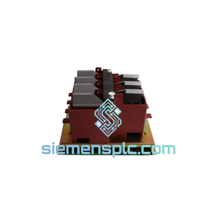
Mechanically, the 3BHB004661R0101 is a PCB-based plug-in module with a keyed connector interface that mechanically prevents incorrect orientation during installation. Signal traces across the board are protected with conformal coating, providing resistance to condensation, humidity up to 95% RH non-condensing, and airborne particulates encountered in paper mills, steel processing facilities, water treatment plants, and marine drive installations. No application-specific parameters or firmware configuration reside on the module — all drive-specific settings are stored on the RDCU control board. Replacement is a direct plug-in swap with no reconfiguration required on the control system side, a characteristic that directly reduces mean time to repair in production-critical applications where every minute of unplanned downtime carries measurable cost. A single 3BHB004661R0101 unit provides spare coverage across ACS800, ACS880, DCS800, and AC800M drive frames, reducing the number of unique spare part numbers required in a mixed-fleet maintenance inventory.
Real-time Stock & RFQ: [email protected] | WhatsApp: +86 18359268345
Technical Parameters
| Parameter | Specification |
|---|---|
| Manufacturer | ABB Group |
| Part Number | 3BHB004661R0101 |
| Board Designation | KUC711AE101 |
| Module Function | IGBT Gate Drive Interface Board |
| Compatible Platforms | ACS800, ACS880, DCS800, AC800M |
| Control Interface | PPCS (Power Package Communication System) — ABB proprietary fiber-optic serial |
| Fiber Medium | Plastic or glass optical fiber (frame-dependent) |
| Isolation Method | Full galvanic isolation via optical fiber; infinite common-mode rejection at signal layer |
| Gate Drive Channels | 6 independent channels — three-phase full inverter bridge (upper + lower per leg) |
| Dead-Time Enforcement | Hardware gate logic — fixed electrical characteristic, independent of CPU task cycle or firmware state |
| Switching Frequency Range | 1–4 kHz (drive platform dependent) |
| DC Bus Voltage Range | Above 600 V DC (ACS800 / ACS880 frame configurations) |
| Primary Fault Detection | Per-channel IGBT desaturation monitoring (V_CE with calibrated turn-on blanking interval) |
| Secondary Fault Detection | Gate drive supply undervoltage per channel |
| Fault Response | Hardware gate blanking + PPCS fault code to RDCU; sub-millisecond response |
| EMC Immunity | Fiber-optic signal path; immune to dV/dt transients up to 10 kV/µs on DC bus |
| Environmental Rating | Conformal coating on signal traces; 95% RH non-condensing |
| Connector Interface | Keyed PCB plug-in — incorrect orientation mechanically prevented |
| On-Board Configuration | None — zero application-specific parameters stored on module |
| Country of Origin | Sweden |
| Supply Condition | Genuine OEM — new or tested surplus (specify at inquiry) |
| Warranty | 12 months from date of dispatch |
Hardware Logical Analysis
PPCS Fiber-Optic Architecture — Isolation Enforced at the Physical Layer: The selection of fiber-optic communication between the RDCU control board and the 3BHB004661R0101 gate unit is an isolation architecture decision, not a bandwidth decision. High-power IGBT drives generate common-mode voltages across the cabinet structure that can reach several hundred volts in microseconds during switching transitions. Copper signal paths crossing the isolation boundary require common-mode chokes, differential signaling, and shielded cabling — each adding impedance, potential failure modes, and maintenance complexity. The PPCS fiber link eliminates this problem at the physical layer. The 3BHB004661R0101 integrates the optical receiver and transmitter directly on the gate drive board, performing optical-to-electrical conversion at the power stage side of the isolation boundary. This yields a signal path with effectively infinite common-mode rejection across the full spectrum of IGBT switching harmonics, with no additional EMC mitigation hardware required between the control board and the gate unit. The fiber medium also provides inherent protection against ground loop currents that can corrupt signal integrity in copper-based inter-board communication within a shared cabinet ground plane.
Hardware Dead-Time Generation — Commutation Determinism Without Software Dependency: In software-managed PWM architectures, dead-time insertion is handled by the processor’s PWM peripheral, introducing a dependency on clock accuracy, interrupt latency, and peripheral register state. The 3BHB004661R0101 removes this dependency by implementing dead-time logic in the gate drive hardware itself. The dead-time interval is determined by the physical characteristics of the gate drive circuit — RC time constants, comparator thresholds, or dedicated logic gate timing — and is therefore invariant with respect to CPU load, PPCS communication latency, or firmware version. For maintenance engineers, this means dead-time behavior is a hardware specification of the gate unit, not a software parameter that can drift or be inadvertently altered during a control board firmware update. This property is particularly significant in multi-drive systems where firmware versions across the fleet may not be uniform, and where a firmware-induced dead-time change could affect commutation behavior across multiple drive frames simultaneously.
Per-Channel Desaturation Detection — Device-Level Protection Ahead of the Current Sensor: Centralized overcurrent protection at the DC bus level — using shunt resistors or Hall-effect current sensors — detects fault conditions only after current has risen to a measurable level and propagated through the measurement circuit and control loop. The 3BHB004661R0101’s per-channel desaturation detection operates at the individual IGBT level, identifying the onset of overcurrent before it reaches the DC bus sensor threshold. The V_CE monitoring circuit is active during each gate drive on-pulse, with a blanking interval at turn-on to allow the device to reach saturation before the measurement is evaluated. The blanking time is a critical design parameter: too short, and normal turn-on transients generate false desaturation faults; too long, and genuine fault conditions are not detected before device damage occurs. ABB’s implementation in the KUC711AE101 reflects accumulated gate drive design experience across multiple generations of the ACS and DCS drive families, with blanking times calibrated to the IGBT characteristics of the supported power stack configurations.
Gate Supply Undervoltage Detection — Linear-Region Dissipation Prevention: An IGBT driven with insufficient gate voltage does not switch cleanly between saturation and cutoff — it operates in its linear (active) region, where collector current is controlled by gate voltage rather than load impedance. In this region, the device dissipates power as the product of V_CE and I_C, which at rated load current and partial gate drive voltage can reach values orders of magnitude above normal switching losses. The 3BHB004661R0101 monitors the gate drive supply voltage for each of its six channels independently. If the supply to any channel falls below the minimum threshold required for full IGBT turn-on, the module immediately reports an undervoltage fault via the PPCS return link. This detection capability is not replicated by any sensor in the DC bus measurement chain, making the gate drive board the only protection layer capable of identifying this specific failure mode before device destruction occurs.
System Integration Benefits
- Hardware-enforced dead-time precision: Commutation timing is a fixed electrical characteristic of the gate drive board, eliminating CPU scheduling jitter as a variable in shoot-through risk for inverter legs operating above 600 V DC bus.
- Full galvanic isolation at the signal layer: PPCS fiber interface provides complete electrical separation between the 24 V control domain and the high-voltage power stage, protecting RDCU and AC800M hardware from DC bus transient coupling without additional isolation components.
- Per-channel hardware fault detection: Desaturation monitoring on each of the six gate drive channels provides device-level protection with sub-millisecond response — faster than any software protection loop in the AC800M control architecture operating on millisecond task cycle times.
- Gate supply undervoltage monitoring: Detects partial IGBT turn-on conditions that cause linear-region power dissipation — a failure mode invisible to DC bus current sensors and capable of destroying devices within seconds if undetected.
- Zero-configuration replacement: No application parameters reside on the module; a direct plug-in swap restores full drive functionality without RDCU reconfiguration, reducing mean time to repair in production-critical installations.
- Multi-platform spare coverage: A single 3BHB004661R0101 unit covers ACS800, ACS880, DCS800, and AC800M drive frames, reducing unique spare part numbers in a mixed-fleet maintenance inventory and simplifying procurement planning.
- Conformal coating for harsh industrial environments: Signal trace protection rated to 95% RH non-condensing extends service life in paper, chemical processing, water treatment, and marine applications without additional enclosure sealing or climate control.
- Keyed mechanical interface: Connector keying mechanically prevents incorrect module orientation during installation — a statistically significant source of installation error in time-pressured breakdown scenarios.
- PPCS fault code transmission and structured logging: Fault events detected at the gate unit are transmitted as coded messages via the PPCS return link and logged by the AC800M control system with timestamps, providing structured data for root-cause analysis and predictive maintenance scheduling.
- Broadband EMC immunity across switching harmonic spectrum: Fiber-optic signal path provides immunity to conducted and radiated interference across the full frequency range of IGBT switching harmonics, with no additional shielding or filtering required between the control board and the gate unit.
Quality Assurance & Global Logistics
Every ABB 3BHB004661R0101 / KUC711AE101 dispatched from siemensplc.com is sourced through documented procurement channels with full traceability to authorized ABB distribution or verified OEM surplus. Pre-dispatch inspection covers physical PCB and connector integrity, label authenticity verification against ABB part numbering conventions, and visual inspection of conformal coating coverage across signal trace areas. Where test equipment compatible with ABB’s PPCS protocol is available, electrical verification is performed prior to dispatch to confirm gate drive channel functionality and fault detection circuit response. Units are packed in anti-static ESD shielding bags, cushioned with closed-cell polyethylene foam inserts, and sealed in double-wall corrugated export cartons rated for international freight handling. Dispatch is from our warehouse in Xiamen, China, with access to DHL Express, FedEx International Priority, and UPS Worldwide Express services. In-stock units ship within 1 to 2 business days of confirmed order. Standard export documentation — commercial invoice, packing list, and certificate of origin — is provided with every shipment to support customs clearance in the EU, USA, Southeast Asia, the Middle East, and South America. All units carry a 12-month warranty covering defects in materials and workmanship from the date of dispatch, with direct technical support from our engineering team throughout the warranty period.
Contact Information
Email: [email protected]
WhatsApp: +86 18359268345
Web: siemensplc.com
Location: Xiamen, China
© 2026 siemensplc.com. All rights reserved.
Ready to quote
[email protected]
Send This Part Number to Sales
RFQ workflow
Quality workflow ->
Confirmation Process
01Model confirmation
We check the full part number, brand, series and visible nameplate information before quotation.
02Availability reply
Sales confirms stock path, condition option, quantity and realistic lead time for export dispatch.
03Packing & courier
DHL, FedEx, UPS or buyer courier arrangements can be reviewed with packing requirements.
Continue sourcing
Browse full catalog ->
Related Automation Parts
Similar brand or category products for fast comparison and multi-item RFQ lists.
ABB
RFQ Ready
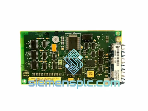
ABB SDCS-COM-5 3BSE006567R1 Fieldbus Communication Module
S800
Origin SE
Fieldbus Communication Module
ABB
RFQ Ready
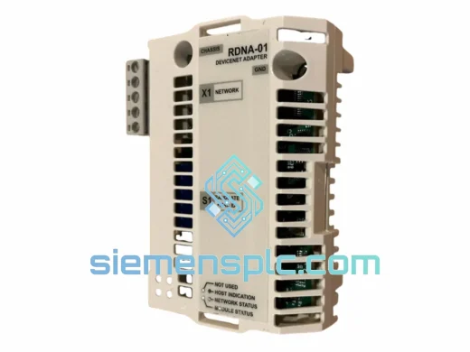
ABB RDNA-01 DeviceNet Adapter Module – ACS800 ACS600
S800
Origin SE
Fieldbus Communication Module
ABB
RFQ Ready
ABB RDCU-12C 3AUA0000036521 Drive Control Unit
S800
Origin SE
PLC & Drive Control Module