
ABB
In Stock OK
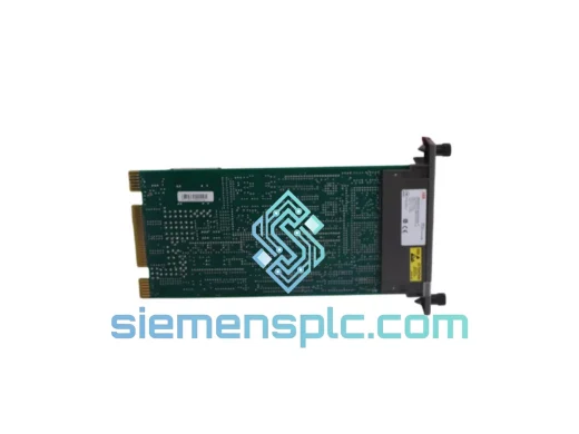
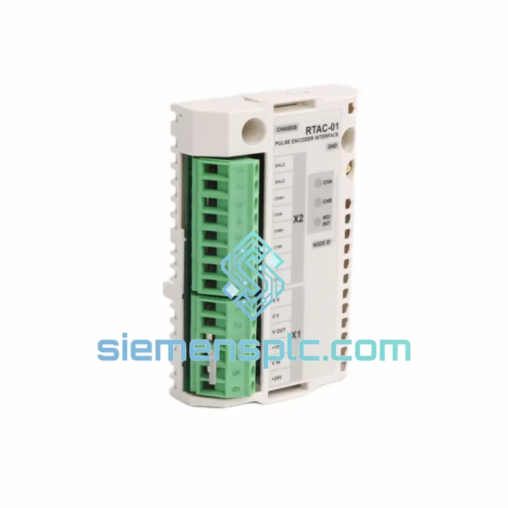
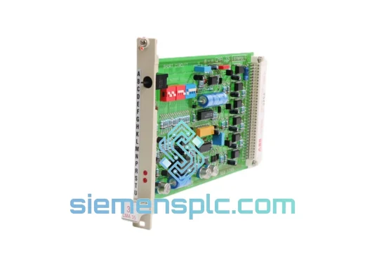
ABB ABBRTAC-01 PLC Interface Module – AC500 Series
Request verified availability, condition, replacement risk review, packing options and courier lead time for ABBRTAC-01.
BrandABB
Part NumberABBRTAC-01
ConditionAvailability Check
Lead TimeRFQ Confirmation
DocumentsDatasheet / photos by RFQ
ShippingExport packing available
Auto-filled RFQ
ABBRTAC-01
Click Request Quote and the part number is inserted into the inquiry form automatically.
- Reply by email: [email protected]
- WhatsApp / Tel: +86 18359268345
- Mon-Sat 9:00-18:00 GMT+8
Procurement Data
Key Product Information
Core fields for model confirmation and RFQ routing. Detailed product narrative remains below.
- Brand
- ABB
- Primary Part Number
- ABBRTAC-01
- Product Type
- PLC Interface Module
- Series / Family
- AC500
- Manufacturer
- ABB
- Country of Origin
- SE
- Catalog Category
- Motor Drives
- Operating Temp.
- 0 °C to +60 °C (horizontal mounting)
- Warranty
- 12 months from date of invoice
- Compliance
- CE, RoHS
Model confirmed for inquiry
ABBRTAC-01
Send quantity, destination and urgency. The RFQ form keeps this part number attached.
Request Quote
Product Overview
ABB ABBRTAC-01 Resolver-to-Digital Interface Module: Signal Conditioning at the Axis Control Boundary
The ABBRTAC-01 occupies a precise and non-negotiable position in closed-loop motion control architectures built on the ABB AC500 PLC platform. Its function is to accept the raw sinusoidal differential output of a resolver — a robust, brushless rotary transformer used extensively in servo and spindle drives — and convert that analog positional signal into a structured digital value that the AC500 CPU can consume within its deterministic scan cycle. Without this conversion stage, the CPU has no reliable mechanism to close a position or velocity loop against a resolver-equipped motor shaft.
Resolvers operate on the principle of electromagnetic induction. A single-phase excitation winding on the rotor is energized at a carrier frequency, typically 2 kHz to 10 kHz. Two stator windings, physically offset by 90°, return amplitude-modulated sine and cosine signals whose ratio encodes absolute shaft angle within one mechanical revolution. The ABBRTAC-01 applies a tracking loop — a second-order phase-locked architecture — to demodulate these signals and extract both angular position and angular velocity simultaneously. The tracking loop bandwidth is tuned to reject carrier-frequency artifacts while maintaining adequate dynamic response for the velocity feedback path.
The module interfaces to the AC500 backplane via the standard S500 I/O bus, which operates at a fixed 1 ms cycle time independent of the number of I/O modules installed. This deterministic bus architecture ensures that the resolver position word is refreshed in the CPU’s process image at every program cycle without jitter introduced by bus arbitration. For motion control tasks where position error accumulation over multiple scan cycles is unacceptable, this fixed-latency data path is a fundamental design requirement rather than a convenience feature.
The ABBRTAC-01 supports resolver excitation output directly from the module, eliminating the need for an external excitation source and reducing wiring complexity in the control cabinet. The excitation amplitude and frequency are factory-set to match the electrical characteristics of standard industrial resolvers, though the module’s compatibility range accommodates the majority of resolver types used in servo drive and CNC spindle applications. The differential signal inputs are designed with high common-mode rejection to suppress noise induced by long cable runs in electrically noisy machine environments.
From a system architecture perspective, the ABBRTAC-01 enables the AC500 to serve as the master position controller in applications where the drive amplifier operates in torque mode, with the PLC closing the outer position and velocity loops in software. This architecture is common in gantry systems, winding machines, and multi-axis coordinated motion applications where the flexibility of PLC-based motion logic outweighs the latency advantages of drive-internal position control. The module’s position data resolution — expressed in bits per revolution — determines the minimum incremental move the control loop can command, which directly affects surface finish quality in machining applications and registration accuracy in printing and converting lines.
All units supplied by siemensplc.com are sourced through verified industrial distribution channels. Each module is inspected for label integrity, connector condition, and factory seal status prior to dispatch. A 12-month warranty against manufacturing defects is provided on every unit.
Real-time Stock & RFQ: [email protected] | WhatsApp: +86 18359268345
Technical Parameters
| Parameter | Value |
|---|---|
| Part Number | ABBRTAC-01 |
| SKU / Order Code | RTAC-01 |
| Manufacturer | ABB |
| Product Series | AC500 S500 I/O |
| Module Function | Resolver-to-Digital Interface |
| Resolver Excitation Output | Sinusoidal, differential, factory-set carrier frequency |
| Input Signal Type | Differential sine/cosine from resolver stator windings |
| Backplane Bus | ABB S500 I/O bus, 1 ms fixed cycle |
| Position Data Format | Digital word, absolute within one revolution |
| Velocity Output | Derived from tracking loop, available in CPU process image |
| Common-Mode Rejection | High CMRR on differential signal inputs |
| Operating Temperature | 0 °C to +60 °C (horizontal mounting) |
| Storage Temperature | -25 °C to +70 °C |
| Relative Humidity | 5 % to 95 %, non-condensing |
| Supply Voltage | 24 V DC via S500 backplane |
| Weight | 80 g |
| Compliance | CE, RoHS |
| Country of Origin | Germany |
| Warranty | 12 months from date of invoice |
Hardware Logical Analysis
The core signal processing chain inside the ABBRTAC-01 begins at the differential input receivers. These receivers present a high impedance to the resolver stator lines, minimizing loading effects that would otherwise distort the amplitude-modulated waveforms and introduce angular error. The common-mode rejection ratio of the input stage suppresses noise voltages that appear equally on both conductors of each differential pair — a critical property when resolver cables share conduit with motor power cables carrying PWM switching transients at frequencies up to several tens of kilohertz.
The demodulation stage extracts the sine and cosine envelope amplitudes from the carrier-modulated inputs. A synchronous demodulation approach, phase-locked to the excitation carrier, provides inherent rejection of out-of-band noise and avoids the amplitude errors that asynchronous peak-detection methods introduce at high shaft velocities. The demodulated sine and cosine values are then fed into the tracking loop.
The tracking loop is a second-order type-II servo loop implemented in digital logic. It tracks the resolver angle by continuously minimizing the error signal derived from the cross-product of the sine and cosine inputs and the estimated angle. The second-order loop characteristic means the loop tracks constant-velocity inputs with zero steady-state error, which is essential for accurate velocity feedback derivation. The loop’s natural frequency and damping ratio are factory-optimized to balance noise bandwidth against dynamic tracking accuracy across the resolver speed range relevant to AC500 motion applications.
EMC hardening at the board level includes decoupling capacitors placed at each power supply pin of every active device, ground plane continuity maintained across the full PCB area, and signal routing that minimizes loop areas in high-frequency signal paths. The module housing provides shielding continuity to the S500 rack ground, ensuring that any shield currents from the resolver cable are returned to the system ground reference at a single defined point rather than flowing through the signal ground of the measurement circuit.
System Integration Benefits
- Deterministic position data latency: The S500 bus delivers the resolver position word to the CPU process image within a fixed 1 ms window, eliminating scan-cycle jitter that would corrupt velocity estimates derived from successive position samples.
- Simultaneous position and velocity feedback: The tracking loop outputs both angular position and angular velocity as independent values, removing the need for the CPU to perform numerical differentiation of position data — a computation that amplifies quantization noise at low shaft speeds.
- Integrated excitation generation: On-module excitation output eliminates a discrete excitation amplifier from the cabinet BOM, reducing component count, wiring terminations, and potential failure points in the signal chain.
- High CMRR input protection: Differential input architecture with high common-mode rejection allows resolver cable runs of practical length in industrial cabinets without signal conditioning repeaters or isolation amplifiers.
- Absolute single-turn position: Resolver-based position measurement is inherently absolute within one mechanical revolution, so the control system retains valid position data through a power cycle without requiring a homing sequence — a significant advantage in applications where homing is time-consuming or mechanically constrained.
- Compatibility with standard resolver types: The module’s input range accommodates the electrical characteristics of the majority of industrial resolvers, reducing the engineering effort required when retrofitting existing resolver-equipped drives into an AC500-based control architecture.
- Diagnostic transparency via AC500 CPU: Module status and fault flags are mapped into the CPU process image alongside position data, enabling the application program to detect resolver open-circuit, signal amplitude faults, and tracking loop overflow conditions without additional diagnostic hardware.
- Scalable multi-axis architecture: Multiple ABBRTAC-01 modules can be installed on a single S500 rack, allowing the AC500 CPU to manage several resolver-equipped axes within one control node — reducing the number of control cabinets and inter-cabinet wiring in multi-axis machine designs.
Quality Assurance & Global Logistics
Every ABBRTAC-01 unit dispatched from siemensplc.com originates from verified ABB distribution channels. Physical inspection covers label authenticity, housing condition, connector pin geometry, and factory seal integrity. Units showing any evidence of remarking, repackaging, or connector damage are rejected before reaching inventory.
Shipments originate from Xiamen, China — a major export hub with direct access to DHL Express, FedEx International Priority, and SF International services. In-stock units are dispatched within 1 to 3 business days of order confirmation. Export documentation — commercial invoice, packing list, and certificate of origin — is prepared for every international shipment. HS code guidance is provided on request to support customs clearance at the destination port. For bulk orders, sea freight consolidation is available with full export licensing support.
A 12-month warranty against manufacturing defects is provided on every unit, covering failure under normal operating conditions as defined in ABB’s published specifications. Warranty claims are processed with a target response time of 48 hours from receipt of the defective unit.
Contact Information
Email: [email protected]
WhatsApp: +86 18359268345
Web: siemensplc.com
Location: Xiamen, China
© 2026 siemensplc.com. All rights reserved.
Ready to quote
[email protected]
Send This Part Number to Sales
RFQ workflow
Quality workflow ->
Confirmation Process
01Model confirmation
We check the full part number, brand, series and visible nameplate information before quotation.
02Availability reply
Sales confirms stock path, condition option, quantity and realistic lead time for export dispatch.
03Packing & courier
DHL, FedEx, UPS or buyer courier arrangements can be reviewed with packing requirements.
Continue sourcing
Browse full catalog ->
Related Automation Parts
Similar brand or category products for fast comparison and multi-item RFQ lists.
ABB
RFQ Ready
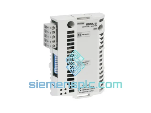
ABB RCNA-01 ControlNet Adapter Module – AC500 Series
AC500
Origin SE
PLC Communication Module
ABB
RFQ Ready
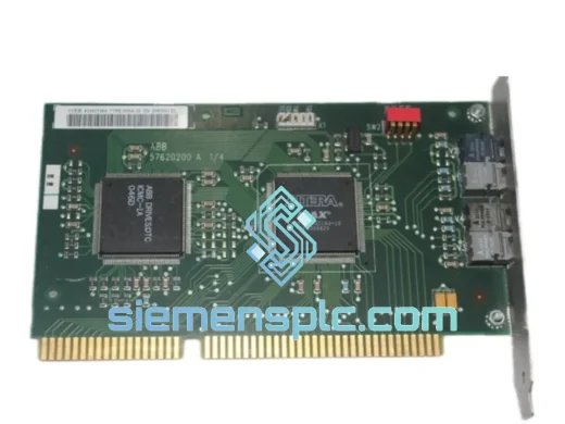
ABB NISA-03 DDCS/ISA Adaptor Module – AC500 / ACS Series
AC500
Origin SE
Communication Adapter Module
ABB
RFQ Ready
ABB CMA35 GVT3605799 Short Circuit Protection Card
AC500
Origin SE
Short Circuit Protection Card