ABB
In Stock OK
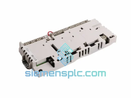
ABB HIEE300927R0101 UBC717AE101 IGBT Gate Drive Board – ACS Series
Request verified availability, condition, replacement risk review, packing options and courier lead time for HIEE300927R0101-UBC717AE101.
BrandABB
Part NumberHIEE300927R0101-UBC717AE101
ConditionAvailability Check
Lead TimeRFQ Confirmation
DocumentsDatasheet / photos by RFQ
ShippingExport packing available
Auto-filled RFQ
HIEE300927R0101-UBC717AE101
Click Request Quote and the part number is inserted into the inquiry form automatically.
- Reply by email: [email protected]
- WhatsApp / Tel: +86 18359268345
- Mon-Sat 9:00-18:00 GMT+8
Procurement Data
Key Product Information
Core fields for model confirmation and RFQ routing. Detailed product narrative remains below.
- Brand
- ABB
- Primary Part Number
- HIEE300927R0101-UBC717AE101
- Product Type
- IGBT Gate Drive Board
- Series / Family
- S800
- Manufacturer
- ABB Ltd. (EU origin)
- Country of Origin
- SE
- Catalog Category
- Motor Drives
- Warranty
- 12 months from shipment date
Model confirmed for inquiry
HIEE300927R0101-UBC717AE101
Send quantity, destination and urgency. The RFQ form keeps this part number attached.
Request Quote
Product Overview
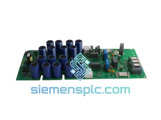
ABB HIEE300927R0101 / UBC717AE101 — IGBT Gate Drive Board: Signal Isolation Architecture and Inverter Control Role
The HIEE300927R0101, carrying sub-designation UBC717AE101, is a purpose-built IGBT gate drive printed circuit board manufactured by ABB for integration into the ACS600, ACS800, and DCS800 medium-voltage variable speed drive families. Within the inverter power stack, this board occupies the interface layer between the drive’s digital control unit — typically the RDCU or RMIO module — and the physical IGBT power modules that switch the DC bus voltage into a pulse-width-modulated AC output. Its function is not peripheral: without a correctly operating gate drive board, the inverter cannot produce controlled output voltage, and the entire drive is non-functional regardless of the state of the control electronics.
In a three-phase ACS800 inverter bridge, each phase leg requires an independent gate drive board. The HIEE300927R0101 receives switching commands from the RDCU via a fiber-optic link, converts those optical pulses into precisely timed ±15 V DC gate signals, and applies them to the gate-emitter terminals of the IGBT module assigned to that phase leg. The timing accuracy of these gate pulses — measured in hundreds of nanoseconds — determines output waveform quality, harmonic content, and the thermal stress distribution across the IGBT silicon. A board operating outside its design parameters introduces asymmetric phase switching, which manifests as elevated motor current ripple, increased acoustic noise, and accelerated bearing wear in connected loads.
For facilities operating continuous processes — chemical dosing, compressor drives, conveyor systems, or HVAC central plant — an unplanned drive outage caused by a failed gate drive board carries a direct cost measured in lost production per hour. Holding a verified, tested spare HIEE300927R0101 on-site reduces mean time to repair from days (procurement lead time) to under one hour (board swap and drive recommission).
Real-time Stock & RFQ: [email protected] | WhatsApp: +86 18359268345
Technical Parameters
| Parameter | Specification |
|---|---|
| ABB Part Number | HIEE300927R0101 |
| Sub-designation | UBC717AE101 |
| Revision Level | R0101 |
| Manufacturer | ABB Ltd. (EU origin) |
| Compatible Drive Platforms | ACS600, ACS800, DCS800 |
| Board Function | IGBT gate drive with fiber-optic signal interface |
| Gate Output Voltage | +15 V DC (turn-on) / −15 V DC (turn-off) |
| Isolation Method | Galvanic isolation via plastic/glass fiber-optic Rx/Tx pair |
| Signal Interface | Fiber-optic, compatible with RDCU / RMIO control units |
| Desaturation Detection | V_CE monitoring, threshold approx. 7–9 V; fault reported via fiber-optic return path |
| Auxiliary Supply Input | From drive power supply board via backplane connector |
| On-board DC-DC Converter | Generates ±15 V gate rails; fixed-frequency synchronous rectification |
| Output Voltage Regulation | ±2 % across full load and temperature range |
| Operating Ambient Temperature | 0 °C to +55 °C (forced-air cooled enclosure) |
| Storage Temperature | −40 °C to +70 °C |
| Relative Humidity (Operating) | 5 % to 95 % RH, non-condensing |
| PCB Weight | 260 g |
| Mounting Format | Guide-rail card slot, drive-specific mechanical envelope |
| EMC Compliance | IEC 61800-3 Category C3 (conducted and radiated) |
| Warranty | 12 months from shipment date |
| Country of Origin | Germany (ABB manufacturing) |
Hardware Logical Analysis
Fiber-Optic Isolation and Common-Mode Rejection: The DC bus voltage in a 690 V AC ACS800 drive reaches approximately 975 V DC under normal operating conditions. During IGBT switching transitions, the collector voltage slews at rates that routinely exceed 5 kV/μs, generating displacement currents through any parasitic capacitance between the power and signal domains. The HIEE300927R0101 eliminates this coupling path entirely by using fiber-optic links for all control signal transmission. Optical fiber has zero electrical conductivity; there is no physical mechanism by which a dV/dt event on the DC bus can inject noise into the gate command signal. This is a qualitatively different isolation approach compared to transformer-coupled or optocoupler-based designs, which retain a small but non-zero inter-winding or junction capacitance that limits common-mode rejection at high switching frequencies.
Gate Output Stage Topology: The board’s gate driver output stage uses a push-pull configuration: a high-side transistor sources current to charge the IGBT gate capacitance during turn-on, while a low-side transistor sinks current to discharge it during turn-off. The gate resistor network — factory-calibrated to the specific IGBT module type installed in the ACS800 power stack — controls the rate of gate voltage rise and fall. A lower gate resistance accelerates switching, reducing conduction losses but increasing the collector-emitter voltage overshoot (V_CE spike) caused by stray inductance in the DC bus bars. ABB’s factory calibration balances these competing constraints within the validated operating envelope. Field modification of gate resistor values without ABB authorization can push V_CE transients above the IGBT’s rated breakdown voltage, causing latent or immediate device failure.
Desaturation Protection Logic: During normal IGBT conduction, the collector-emitter voltage (V_CE(sat)) is typically 1.5–3.5 V depending on collector current and junction temperature. If the IGBT fails to fully saturate — due to a gate drive fault, excessive collector current, or device degradation — V_CE rises sharply. The HIEE300927R0101 monitors V_CE through a high-voltage sensing circuit and compares it against a fixed threshold of approximately 7–9 V. When the threshold is exceeded, the board immediately asserts a fault signal on the fiber-optic return path to the RDCU. The RDCU responds by executing a soft-shutdown sequence — ramping down the PWM duty cycle rather than abruptly blocking all gate pulses — to limit the di/dt-induced voltage spike that would otherwise occur if the IGBT were switched off at full collector current. This hardware-level protection loop operates with a response time measured in microseconds, independent of the drive’s main control software execution cycle.
EMC PCB Layout Strategy: The board’s multilayer PCB separates high-current gate drive traces from low-level signal traces using dedicated copper planes. Decoupling capacitors with low equivalent series resistance (ESR) are placed within 2 mm of each power supply pin on the gate driver ICs, minimizing the impedance of the local supply loop at switching frequencies. The fiber-optic transceiver housings are mechanically referenced to the PCB ground plane, preventing the transceiver body from acting as an antenna. These layout measures collectively ensure that the board’s own switching activity does not generate conducted or radiated emissions that would interfere with the RDCU’s signal processing or with adjacent control cards in the drive cabinet.
Auxiliary Power Supply Architecture: The on-board DC-DC converter accepts the unregulated auxiliary voltage supplied by the drive’s power supply board and generates the ±15 V rails required by the gate driver output stage. The converter operates at a fixed switching frequency above 100 kHz, placing its fundamental and harmonic emissions well above the drive’s PWM carrier frequency (typically 1–3 kHz for ACS800 DTC operation). This frequency separation prevents beat-frequency interference between the auxiliary converter and the main inverter modulation. Synchronous rectification on the secondary side reduces rectifier conduction losses, maintaining converter efficiency above 85 % across the full load range and limiting self-heating within the board’s thermal budget.
System Integration Benefits
- Fixed fiber-optic propagation delay enables precise dead-time compensation: Unlike copper signal paths whose propagation delay varies with temperature and supply voltage, optical fiber delay is constant. The RDCU uses this fixed delay as a known offset when calculating the dead-time interval between complementary IGBT switching events, reducing output voltage distortion at low modulation indices where dead-time error is proportionally largest.
- Board-level fault codes reduce diagnostic time: The desaturation detection circuit reports faults with a specific fault code (e.g., FF-52 or equivalent per drive firmware version) rather than a generic overcurrent trip. Maintenance personnel can identify the faulted phase leg and the specific board within minutes, compared to hours of systematic elimination required when only a generic fault is available.
- Standardized card format minimizes MTTR: The HIEE300927R0101 conforms to ABB’s defined card dimensions and backplane connector pinout for the ACS800 power stack. Replacement requires no mechanical modification, no re-wiring, and no recalibration of drive parameters — the drive’s commissioning data remains valid after a board swap, allowing restart within the time required to physically exchange the card and cycle drive power.
- Accurate gate timing reduces IGBT junction temperature rise: Switching losses in an IGBT are proportional to the switching frequency and the energy dissipated per switching event. Correct gate drive timing minimizes both turn-on and turn-off energy losses, keeping junction temperature below the module’s rated maximum. Over a continuous 24/7 operating profile, a 5 °C reduction in average junction temperature approximately doubles the expected IGBT module service life according to standard power cycling fatigue models.
- Modular phase-leg architecture supports partial maintenance: In ACS800 multi-drive or parallel inverter configurations, each phase leg uses an independent HIEE300927R0101 board. A single board can be replaced without disturbing the adjacent phase legs, allowing maintenance to be performed on one phase while the remaining phases are isolated — a capability that supports partial-redundancy maintenance strategies in drives with bypass arrangements.
- DriveWindow / DriveMonitor integration provides fault history logging: The RDCU timestamps and logs each gate drive fault event with fault code, duration, and drive operating state at the time of fault. This data is accessible via ABB’s DriveWindow or DriveMonitor PC tools, enabling maintenance teams to identify recurring fault patterns — such as a board that trips intermittently under high ambient temperature — before a complete failure occurs.
- Single revision covers three drive platforms: Revision R0101 of the HIEE300927R0101 is validated for use in ACS600, ACS800, and DCS800 platforms. A facility operating multiple ABB drive types can maintain a single spare part number to cover all three platforms, reducing spare parts inventory complexity and the associated carrying cost.
- DTC switching sequence compatibility preserves torque control performance: ABB’s Direct Torque Control algorithm generates irregular, non-carrier-synchronized switching patterns with switching events that can occur at any point within the control cycle. The HIEE300927R0101’s fiber-optic interface and gate driver response time are specified to handle these aperiodic switching commands without introducing timing errors that would degrade torque ripple or flux estimation accuracy in DTC-controlled drives.
Quality Assurance & Global Logistics
Each HIEE300927R0101 unit dispatched from siemensplc.com is sourced through ABB’s authorized distribution network or verified secondary market channels with documented batch traceability. Before any unit is offered for sale, it passes a structured inspection sequence: visual examination of PCB surface finish, solder joint integrity, and component seating under 10× magnification; continuity verification of all signal and power traces against the reference netlist; functional test of the fiber-optic Rx/Tx pair at rated optical power levels; and gate output voltage measurement under resistive load at both ±15 V rails. Units that deviate from ABB’s original performance specifications at any inspection stage are quarantined and not released for sale.
Packaging follows IEC 61340-5-1 electrostatic discharge protection requirements: each board is sealed in a conductive poly bag with a humidity indicator card and silica gel desiccant, then cushioned within a foam-lined corrugated carton rated for IATA air freight handling. Our dispatch facility in Xiamen, China provides direct access to DHL Express, FedEx International Priority, and UPS Worldwide services. Typical transit times are 3–5 business days to Europe and North America, 2–4 business days to Southeast Asia, and 4–7 business days to the Middle East and South America. Orders confirmed before 14:00 CST are eligible for same-day dispatch. Each shipment includes a commercial invoice, packing list, and certificate of conformance. Export documentation is prepared under HS Code 8537.10 in compliance with destination country import regulations, with declared value and country of origin stated accurately to avoid customs delays.
A 12-month warranty covers all units against manufacturing defects and functional failure under normal operating conditions as defined by ABB’s application guidelines. Warranty claims are acknowledged within 24 hours of receipt and processed within 5 business days of return unit inspection, with replacement unit dispatch or full refund issued at the customer’s election.
Contact Information
Email: [email protected]
WhatsApp: +86 18359268345
Web: siemensplc.com
Location: Xiamen, China
© 2026 siemensplc.com. All rights reserved.
Ready to quote
[email protected]
Send This Part Number to Sales
RFQ workflow
Quality workflow ->
Confirmation Process
01Model confirmation
We check the full part number, brand, series and visible nameplate information before quotation.
02Availability reply
Sales confirms stock path, condition option, quantity and realistic lead time for export dispatch.
03Packing & courier
DHL, FedEx, UPS or buyer courier arrangements can be reviewed with packing requirements.
Continue sourcing
Browse full catalog ->
Related Automation Parts
Similar brand or category products for fast comparison and multi-item RFQ lists.
ABB
RFQ Ready
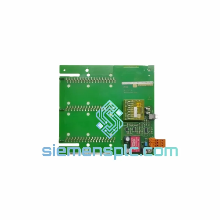
ABB SDCS-COM-5 3BSE006567R1 Fieldbus Communication Module
S800
Origin SE
Fieldbus Communication Module
ABB
RFQ Ready
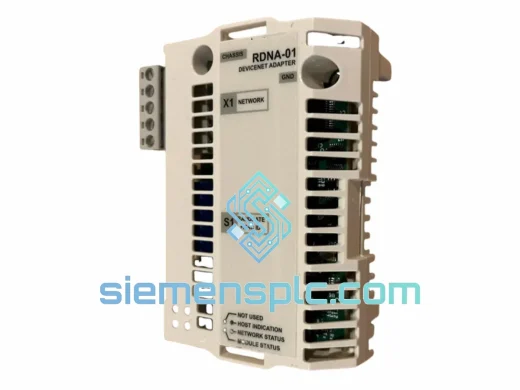
ABB RDNA-01 DeviceNet Adapter Module – ACS800 ACS600
S800
Origin SE
Fieldbus Communication Module
ABB
RFQ Ready
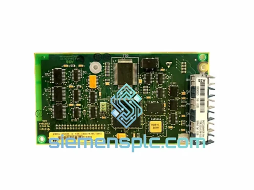
ABB RDCU-12C 3AUA0000036521 Drive Control Unit
S800
Origin SE
PLC & Drive Control Module