Basler Electric
RFQ Ready
BASLER DGC-2020HD MGC-3020 X59434200300 Digital Genset Controller – DGC Series
Origin Not specified
Digital Genset Controller
Request verified availability, condition, replacement risk review, packing options and courier lead time for DECS-250-LN1SN1N.
Click Request Quote and the part number is inserted into the inquiry form automatically.
Core fields for model confirmation and RFQ routing. Detailed product narrative remains below.
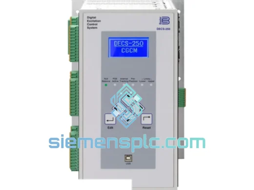
The Basler Electric DECS-250-LN1SN1N is a 32-bit DSP-based digital excitation control system designed for synchronous generators deployed in utility interconnection, industrial co-generation, marine propulsion support, and mission-critical standby power installations. Within the generator control architecture, the automatic voltage regulator (AVR) occupies the innermost feedback loop: it continuously compares measured terminal voltage against a programmable setpoint and adjusts field current output to eliminate the error. The speed, accuracy, and protection coordination of this loop determine whether the generator remains a stable voltage source or becomes a source of reactive power oscillation and potential loss of synchronism.
The model suffix LN1SN1N is a factory-encoded hardware configuration string. Decoded: single-phase voltage sensing input (L), standard field output bridge (N1), RS-232 front-panel communication port (S), RS-485 rear-terminal Modbus port (N1), and no optional expansion card installed (N). This suffix must be verified against the generator’s excitation system wiring diagram before procurement, as the sensing input topology and communication port complement are fixed at the factory and cannot be field-modified without a hardware revision.
Basler Electric has manufactured excitation control equipment since 1942. The DECS-250 platform is the current-generation architecture, replacing the DECS-200 series with a wider operating temperature range, expanded protection function set, and higher-throughput communication stack. The DECS-250-LN1SN1N is deployed across hydro turbine generators, gas turbine gensets, diesel prime movers, and synchronous condensers used for reactive power compensation on industrial and utility buses.
Real-time Stock & RFQ: [email protected] | WhatsApp: +86 18359268345
| Parameter | Specification |
|---|---|
| Part Number | DECS-250-LN1SN1N |
| Platform Series | DECS-250 (Digital Excitation Control System, 3rd Generation) |
| Manufacturer | Basler Electric Co., Highland, Illinois, USA |
| Control Processor | 32-bit fixed-point DSP |
| Control Modes | AVR, FCR (Field Current Regulation), VAR control, Power Factor (PF) control |
| Voltage Sensing Configuration | Single-phase AC input (suffix: L); nominal sensing range 0–240 V AC |
| Voltage Regulation Accuracy | ±0.25% of setpoint, steady-state, rated load and temperature |
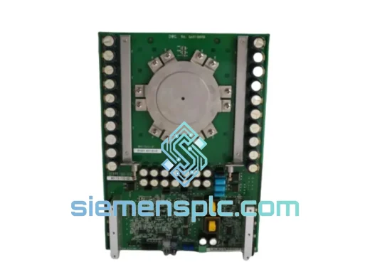
| Field Output Stage | Phase-controlled SCR bridge; continuous DC field current output |
| Soft-Start Ramp | Configurable 2–10 seconds; limits field current rise rate at startup |
| Communication — Port 1 | RS-232, front panel (DB-9); BESTCOMSPlus® configuration and oscillography |
| Communication — Port 2 | RS-485, rear terminal block; Modbus RTU slave protocol |
| Protection Functions | OEL (over-excitation limiter), UEL (under-excitation limiter), LOS (loss of sensing), V/Hz limiter, over-voltage, under-voltage, soft-start |
| Auxiliary Power Input | 85–264 V AC, 47–63 Hz universal input (or DC auxiliary per variant) |
| Operating Temperature | −20 °C to +65 °C |
| Storage Temperature | −40 °C to +70 °C |
| Relative Humidity | 5%–95% RH, non-condensing |
| Mounting Style | Panel mount; DIN rail adapter accessory available |
| Enclosure Protection | IP20 (for installation inside a control panel enclosure) |
| Unit Weight | Approx. 420 g |
| Regulatory Compliance | CE marked; UL recognized component |
| Warranty | 12 months from shipment date |
Analog Front-End and RMS Computation: The single-phase sensing input (L suffix) routes the generator terminal voltage through a precision step-down transformer and a dedicated analog conditioning stage. The conditioned signal is digitized by a high-resolution ADC integrated into the DSP peripheral set. RMS voltage calculation is executed entirely in firmware using a sliding-window integration algorithm, eliminating the temperature drift and gain error inherent in analog RMS-to-DC converter ICs used in first- and second-generation AVRs. The result is a feedback signal whose accuracy is bounded by ADC resolution and firmware arithmetic precision rather than passive component tolerances — a meaningful advantage in installations where ambient temperature varies across the full −20 °C to +65 °C operating envelope.
DSP Control Loop Execution Rate and Bandwidth: The 32-bit DSP executes the PID voltage regulation algorithm at a fixed interrupt rate in the 1–4 kHz range, depending on firmware revision. This execution rate is two to three orders of magnitude faster than the generator field winding’s electrical time constant (T’do typically 0.5–10 seconds for salient-pole and round-rotor machines). The resulting control bandwidth is sufficient to track sub-cycle voltage deviations caused by load steps, fault clearance transients, and grid disturbances without requiring the oversized gain margins that analog AVRs require to maintain stability. PID coefficients (Kp, Ki, Kd) are independently adjustable via BESTCOMSPlus® to match the specific generator’s open-circuit time constant and transient reactance (X’d), enabling stable operation across a wide range of machine ratings without hardware changes.
Field Output Stage — SCR Bridge and Gate Drive Logic: The field output stage employs a phase-controlled silicon-controlled rectifier (SCR) bridge. The DSP computes the required firing angle each half-cycle based on the PID output, and the gate drive circuit delivers synchronized trigger pulses to the SCR gates. This architecture provides continuous, linear control of average field voltage from zero to the rated ceiling value without the discrete steps or dead-band artifacts associated with relay-switched field resistor networks. The SCR bridge’s inherent commutation characteristic also provides a degree of current limiting during field forcing conditions, protecting the field winding from sustained overcurrent before the OEL software function intervenes.
EMC Architecture and Isolation Strategy: Generator control panels present a high-severity electromagnetic environment: contactor switching transients, thyristor drive harmonics, and bus fault current derivatives can generate conducted disturbances exceeding IEC 61000-4-4 Level 3 (4 kV peak) and radiated fields exceeding IEC 61000-4-3 Level 3 (10 V/m). The DECS-250-LN1SN1N addresses this through optical isolation at all digital I/O interfaces, breaking galvanic ground loops between the controller logic ground and external relay panel wiring. The RS-485 port uses balanced differential signaling with a common-mode rejection ratio sufficient to maintain data integrity on cable runs up to 1,200 m in the presence of common-mode noise from adjacent power cables. Internal switch-mode power supply filtering and board-level copper shielding suppress conducted emissions from the SCR gate drive and field output circuits back onto the auxiliary power bus.
Protection Coordination — OEL, UEL, and LOS Logic: The over-excitation limiter (OEL) implements an inverse-time thermal model of the generator field winding. When field current exceeds the continuous rating, the OEL integrates the thermal accumulation and begins reducing the AVR setpoint along a curve that mirrors the field winding’s I²t characteristic, permitting brief field forcing during fault ride-through while preventing sustained thermal damage. The under-excitation limiter (UEL) enforces a reactive power absorption boundary that tracks the generator’s steady-state stability limit, preventing operation in the leading power factor region where loss of synchronism risk increases. The loss-of-sensing (LOS) function monitors the sensing input for open-circuit or short-circuit conditions; upon detection, it transfers control to FCR mode at the last valid field current level, preventing an uncontrolled voltage excursion during a potential transformer fuse failure or sensing wiring fault — a failure mode that has caused generator trips in installations using AVRs without this function.
Each DECS-250-LN1SN1N unit offered through siemensplc.com is sourced through verified supply channels with documented traceability to Basler Electric’s manufacturing output. Basler Electric produces the DECS-250 Series under an ISO 9001-certified quality management system at its Highland, Illinois facility, with 100% functional testing of each unit prior to factory shipment and test records retained in the production database.
At our Xiamen, China operations center, every inbound unit undergoes a secondary inspection protocol covering physical integrity, label and serial number authentication, connector and terminal condition, and model suffix verification against the ordered configuration. Units that fail any inspection criterion are quarantined and removed from available inventory — they are not offered for sale under any circumstances.
Outbound international shipments depart Xiamen via DHL Express, FedEx International Priority, and UPS Worldwide Express. Standard export documentation — commercial invoice, packing list, certificate of origin, and HS code declaration — accompanies every shipment. In-stock units confirmed before 14:00 CST are eligible for same-day dispatch. Indicative transit times: Europe 3–5 business days; North America 4–6 business days; Southeast Asia 2–3 business days; Middle East 4–7 business days. Volume orders are accommodated via freight forwarder consolidation with advance scheduling.
A 12-month warranty from the date of shipment covers manufacturing defects and component failures under rated operating conditions. Warranty claims receive an initial response within 48 hours, and replacement units are dispatched from Xiamen stock where available to minimize site downtime.
Email: [email protected]
WhatsApp: +86 18359268345
Web: siemensplc.com
Location: Xiamen, China
© 2026 siemensplc.com. All rights reserved.
We check the full part number, brand, series and visible nameplate information before quotation.
Sales confirms stock path, condition option, quantity and realistic lead time for export dispatch.
DHL, FedEx, UPS or buyer courier arrangements can be reviewed with packing requirements.
Similar brand or category products for fast comparison and multi-item RFQ lists.