Bently Nevada
RFQ Ready
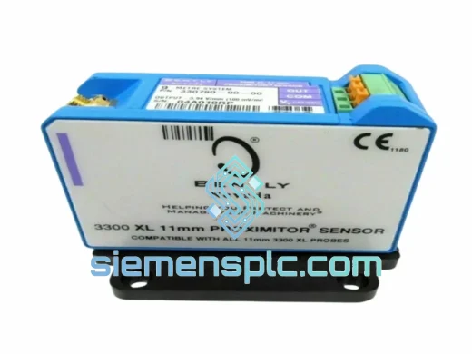
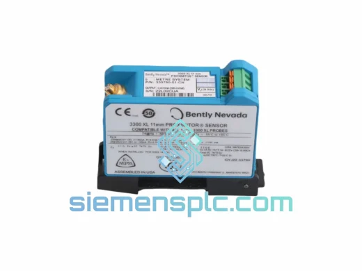
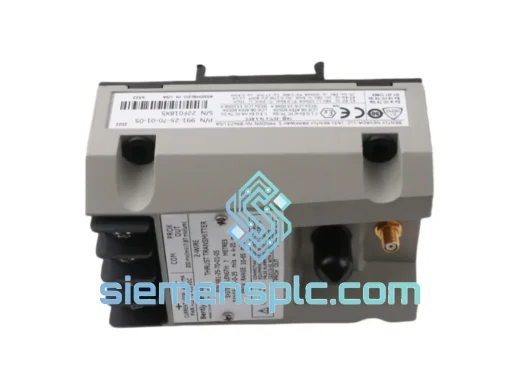
Bently Nevada 991-25-70-01-01 Proximity Probe Extension Cable – 3300 XL Series
3300 XL
Origin US
Proximity Probe Extension Cable
Request verified availability, condition, replacement risk review, packing options and courier lead time for 21000-34-10-00-066-04-02.
Click Request Quote and the part number is inserted into the inquiry form automatically.
Core fields for model confirmation and RFQ routing. Detailed product narrative remains below.
In continuous-duty rotating machinery — steam turbines, centrifugal compressors, boiler feed pumps — the mechanical integrity of the proximity probe mounting assembly is not a secondary concern. It is the primary determinant of measurement fidelity. A probe tip displaced by even 0.05 mm from its calibrated gap position introduces a DC offset error that propagates through the entire signal chain, corrupting both radial vibration and axial position readings simultaneously. The Bently Nevada 21000-34-10-00-066-04-02 Proximity Probe Housing Assembly eliminates this failure mode by providing a dimensionally stable, thermally compensated mounting structure engineered to maintain probe-to-shaft gap geometry across the full operating envelope of the machine.
This assembly is a factory-configured component within the Bently Nevada 3300 XL Proximity Transducer System — the eddy current measurement platform that has accumulated more than four decades of field validation in API 670-governed machinery protection installations. The part number encodes a specific combination of probe body length, cable exit orientation, thread specification, and mounting flange geometry. Each digit segment in the 21000-34-10-00-066-04-02 designation maps to a defined mechanical parameter, making cross-substitution with adjacent part numbers technically inadvisable without engineering review. This is an OEM-grade replacement component, not a generic housing.
The 3300 XL system operates on the principle of high-frequency eddy current induction: the probe tip generates an oscillating electromagnetic field at approximately 1 MHz. When a conductive target (the rotating shaft) enters the field, eddy currents are induced on the shaft surface, loading the oscillator circuit and producing a voltage output linearly proportional to the gap distance. The housing assembly’s role is to hold the probe coil at a fixed, mechanically repeatable position relative to the shaft centerline — typically within a gap range of 0.25 mm to 2.54 mm (10 to 100 mils) — while isolating the probe body from process vibration, thermal expansion of the bearing housing, and installation torque that could otherwise rotate the probe tip out of its calibrated orientation.
Real-time Stock & RFQ: [email protected] | WhatsApp: +86 18359268345
| Parameter | Specification |
|---|---|
| Part Number | 21000-34-10-00-066-04-02 |
| Brand | Bently Nevada (Baker Hughes) |
| Series | 3300 XL Proximity Transducer System |
| Component Type | Proximity Probe Housing Assembly |
| Sensing Principle | Eddy Current (Non-contact, inductive) |
| Nominal Operating Frequency | ~1 MHz (oscillator carrier frequency) |
| Calibrated Gap Range | 0.25 – 2.54 mm (10 – 100 mils) |
| Linear Range (typical) | 0.5 – 2.0 mm (20 – 80 mils) |
| Scale Factor | 7.87 V/mm (200 mV/mil) — system-level, driver-dependent |
| Probe Body Material | 316 Stainless Steel |
| Temperature Range (operating) | –35°C to +177°C (–31°F to +351°F) |
| Pressure Rating | Per housing configuration; consult datasheet for sealed variants |
| Compliance Standard | API 670 (Machinery Protection Systems) |
| Compatible Monitor Platform | Bently Nevada 3300 XL, 3500 Series |
| Weight | Approx. 1,400 g (complete assembly) |
| Country of Origin | United States |
| Warranty | 12 months from date of shipment |
The mechanical design of the 21000-34-10-00-066-04-02 housing addresses three distinct failure vectors that degrade eddy current measurement accuracy in field installations:
Thermal Differential Expansion Management: Bearing housings in high-speed turbomachinery operate at sustained temperatures between 80°C and 150°C. The housing assembly uses a matched-coefficient material stack — 316 stainless steel probe body interfacing with a carbon steel or stainless mounting boss — to minimize differential thermal expansion between the probe tip and the bearing housing bore. Without this thermal compensation, a 70°C temperature rise across a mismatched material pair could produce a gap shift of 15–25 μm, equivalent to a false vibration reading of 3–5 mils pk-pk at the monitor output.
Anti-Rotation Locking Geometry: The housing incorporates a mechanical anti-rotation feature — typically a locknut and jam-nut arrangement with a defined torque specification — that prevents probe body rotation under sustained vibration. Probe rotation in an installed assembly changes the effective gap by altering the thread engagement depth, introducing a systematic DC offset that is indistinguishable from actual shaft position change at the monitor level. The 21000-34-10-00-066-04-02 assembly’s thread geometry and locking mechanism are designed to maintain probe position within ±0.013 mm (±0.5 mil) under continuous vibration exposure per API 670 qualification testing.
EMC Shielding Architecture: The probe cable within the housing assembly uses a coaxial construction with a continuous outer shield bonded to the housing body at the cable exit point. This shield continuity prevents common-mode noise injection from adjacent high-voltage cabling, variable frequency drives, or motor starters — all of which are present in typical turbomachinery control rooms. The shield is grounded at the Proximitor sensor end only (single-point grounding), eliminating ground loop currents that would appear as low-frequency noise on the vibration signal. In installations where VFD switching frequencies (typically 2–16 kHz) are present, this shielding architecture provides greater than 40 dB of common-mode rejection across the relevant frequency band.
Probe Tip Geometry Preservation: The housing nose piece protects the probe coil winding from mechanical contact during installation and from particulate contamination in oil-mist environments. The coil winding geometry — specifically the coil diameter-to-gap ratio — is the primary determinant of the probe’s sensitivity and linearity. Any deformation of the coil form changes the electromagnetic field distribution and shifts the calibration curve, requiring full system recalibration. The housing’s nose geometry provides a defined mechanical stop that prevents over-insertion of the probe tip into the bearing housing bore.
Every Bently Nevada 21000-34-10-00-066-04-02 unit supplied by siemensplc.com is sourced through verified industrial supply channels with full traceability to the original Baker Hughes manufacturing documentation. Each assembly undergoes the following pre-shipment verification protocol at our Xiamen, China facility:
Shipments from Xiamen, China reach major industrial hubs via DHL Express, FedEx International Priority, and UPS Worldwide Expedited. Typical transit times: Southeast Asia 2–3 days, Middle East 3–4 days, Europe 4–5 days, North America 5–7 days. Export documentation for customs clearance — including HS code classification, country of origin certificates, and end-user declarations — is prepared as standard for all international orders.
Email: [email protected]
WhatsApp: +86 18359268345
Web: siemensplc.com
Location: Xiamen, China
© 2026 siemensplc.com. All rights reserved.
We check the full part number, brand, series and visible nameplate information before quotation.
Sales confirms stock path, condition option, quantity and realistic lead time for export dispatch.
DHL, FedEx, UPS or buyer courier arrangements can be reviewed with packing requirements.
Similar brand or category products for fast comparison and multi-item RFQ lists.