Bently Nevada
RFQ Ready
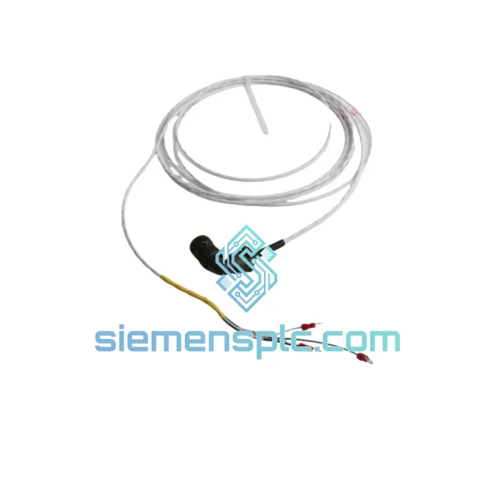
Bently Nevada 991-25-50-01-00 Thrust Transmitter – 3500 Series
3500 Series
Origin US
Thrust Transmitter
Request verified availability, condition, replacement risk review, packing options and courier lead time for 89477-20.
Click Request Quote and the part number is inserted into the inquiry form automatically.
Core fields for model confirmation and RFQ routing. Detailed product narrative remains below.
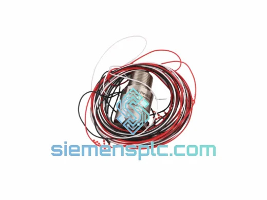
The Bently Nevada 89477-20 is the factory-specified rack-level interconnect cable engineered exclusively for the 3500 Series Machinery Protection System. Within a continuous online protection architecture, the signal path between field transducers and the 3500 rack I/O modules is the most electrically vulnerable segment of the measurement chain. Proximity probe outputs operate in the millivolt range; velocity transducer signals carry phase-critical waveform data that the monitor card processes at update rates below 100 ms. Any impedance mismatch, shield discontinuity, or connector contact resistance introduced at this junction directly corrupts the vibration amplitude and phase readings that machinery protection decisions depend on. The 89477-20 eliminates these variables by providing a fully characterized, OEM-matched signal path with verified electrical parameters.
This cable is not a generic shielded assembly. Its conductor gauge, dielectric material, shield coverage geometry, and connector termination scheme are co-designed with the 3500 rack input impedance specification. The result is a cable that maintains signal fidelity across the full operating frequency range of the 3500 monitor cards — from low-frequency shaft bow detection at 0.1 Hz through high-frequency blade-pass events exceeding 10 kHz — without requiring calibration offsets or signal conditioning compensation at the software layer.
Real-time Stock & RFQ: [email protected] | WhatsApp: +86 18359268345
| Parameter | Specification |
|---|---|
| Part Number | 89477-20 |
| Manufacturer | Bently Nevada (Baker Hughes) |
| Compatible Platform | 3500 Series Machinery Protection System |
| Cable Classification | Rack-Level Shielded Interconnect |
| Shield Construction | Dual-layer: aluminum-polyester foil + tinned copper braid |
| Shield Coverage | ≥ 95% optical coverage (braid layer) |
| Conductor Material | Stranded tinned copper |
| Dielectric | Low-loss polyethylene (PE) insulation |
| Characteristic Impedance | Matched to 3500 rack input specification |
| Operating Temperature | -20 °C to +70 °C (ambient) |
| Connector Type | OEM-keyed, polarity-safe multi-pin |
| Jacket Material | PVC, flame-retardant grade |
| Approximate Weight | 900 g |
| Country of Origin | United States |
| Warranty | 12 months from date of dispatch |
The 89477-20 addresses three distinct hardware-level failure modes that are endemic to non-OEM rack interconnect cables in rotating machinery monitoring installations.
EMC Design and Common-Mode Noise Rejection: Industrial plant environments surrounding turbomachinery generate broadband electromagnetic interference from variable-frequency drives, high-current bus bars, and switched-mode power supplies. The 89477-20 employs a dual-layer shield architecture — an inner aluminum-polyester foil bonded to the dielectric, plus an outer tinned copper braid — that provides attenuation across both low-frequency magnetic field coupling and high-frequency capacitive coupling paths. The foil layer presents a continuous, low-resistance barrier to electric field ingress; the braid layer provides the low-impedance ground return path that prevents shield current from developing a voltage differential at the rack input terminal. This two-layer geometry achieves common-mode rejection ratios that a single-shield cable cannot match, particularly in the 50 Hz to 10 kHz band where machinery vibration harmonics and plant electrical noise overlap.
Connector Contact Resistance and Thermal Stability: The OEM-keyed connector body uses gold-plated contact pins with a defined normal force specification. Contact resistance below 10 mΩ per pin is maintained across the rated temperature range, preventing thermocouple-effect EMF generation at dissimilar-metal junctions — a known source of DC offset error in proximity probe signal chains. The keyed housing geometry enforces correct pin alignment during blind mating in confined rack enclosures, eliminating the partial-insertion contact failures that cause intermittent signal dropout during vibration events.
Impedance Continuity and Capacitance Matching: The 3500 monitor card input stage presents a defined load impedance. A cable with mismatched characteristic impedance creates a reflection coefficient at the termination point, introducing standing-wave amplitude errors at frequencies above approximately 1 kHz. For blade-pass frequency monitoring on high-speed compressors operating at 10,000–20,000 RPM, this error is not negligible. The 89477-20’s dielectric geometry is dimensioned to match the OEM impedance specification, ensuring that the monitor card’s internal calibration constants remain valid without field correction.
Every 89477-20 unit dispatched from our Xiamen, China facility undergoes a structured pre-shipment verification protocol. Connector pin continuity is verified across all conductors using a calibrated low-resistance ohmmeter. Shield integrity is confirmed by measuring shield-to-conductor insulation resistance at 500 VDC — a value that must exceed 100 MΩ to pass. The cable jacket and connector body markings are visually inspected against OEM reference documentation to confirm part number authenticity. Units are individually packaged in anti-static polyethylene bags, placed in rigid corrugated cartons with foam cushioning, and labeled with the part number, serial reference, and dispatch date.
International shipments are processed via DHL Express, FedEx International Priority, and UPS Worldwide Expedited, with typical transit times of 3–5 business days to Europe, North America, Southeast Asia, and the Middle East. Commercial invoices, packing lists, and certificates of origin are prepared for all export shipments. For projects requiring expedited customs clearance, pre-classified HS code documentation is available on request. All units carry a 12-month warranty covering manufacturing defects in materials and workmanship, with advance replacement available for critical-path maintenance scenarios.
Email: [email protected]
WhatsApp: +86 18359268345
Web: siemensplc.com
Location: Xiamen, China
© 2026 siemensplc.com. All rights reserved.
We check the full part number, brand, series and visible nameplate information before quotation.
Sales confirms stock path, condition option, quantity and realistic lead time for export dispatch.
DHL, FedEx, UPS or buyer courier arrangements can be reviewed with packing requirements.
Similar brand or category products for fast comparison and multi-item RFQ lists.