Bently Nevada
RFQ Ready
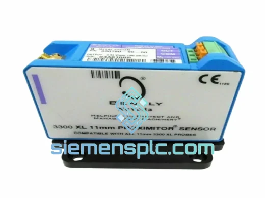
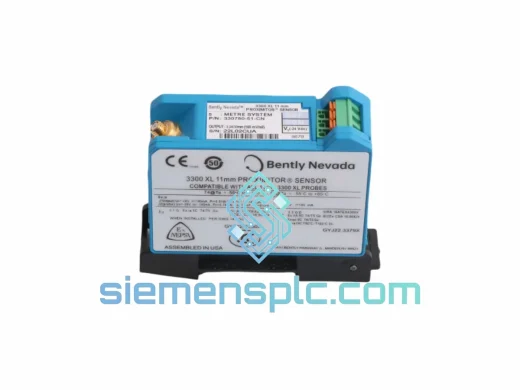
Bently Nevada 991-25-70-01-01 Proximity Probe Extension Cable – 3300 XL Series
3300 XL
Origin US
Proximity Probe Extension Cable
Request verified availability, condition, replacement risk review, packing options and courier lead time for 990-04-50-01-00.
Click Request Quote and the part number is inserted into the inquiry form automatically.
Core fields for model confirmation and RFQ routing. Detailed product narrative remains below.
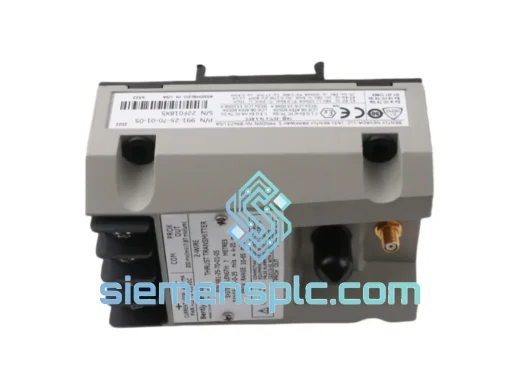
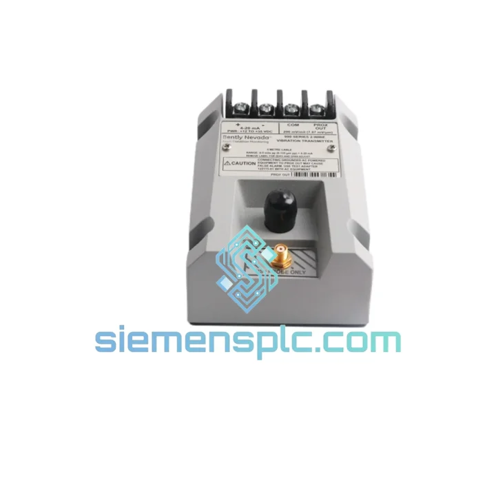
The 990-04-50-01-00 occupies a precisely defined position in the rotating machinery monitoring signal chain: it accepts the raw DC voltage output of a 3300 XL 8 mm Proximitor sensor assembly — connected via a 5-metre (16.4 ft) extension cable — and delivers a standardised 4–20 mA analogue current signal to the plant distributed control system (DCS) or safety instrumented system (SIS). This conversion step is not cosmetic. The Proximitor output is a high-impedance, negative-polarity DC voltage that cannot be transmitted over long cable runs without susceptibility to resistive loading errors and common-mode interference pickup. The 990-series transmitter resolves both constraints simultaneously: its high-impedance differential input stage presents a load of less than 10 kΩ to the Proximitor output, preventing measurement error from source loading, while its current-mode output is inherently immune to resistive cable losses across runs up to 600 Ω loop impedance.
The measurement relationship is defined by the 3300 XL 8 mm probe’s calibrated sensitivity of 7.87 V/mm (200 mV/mil). Over the linear operating range of 0.25 mm to 2.25 mm probe-to-shaft gap, the Proximitor output traverses from approximately −2 VDC to −18 VDC. The 990-04-50-01-00 maps this 16 V input span to a 16 mA output span (4 mA to 20 mA), yielding a transfer coefficient of 1 mA per volt of Proximitor output — a ratio that simplifies DCS scaling configuration and eliminates the need for non-standard input range entries in the analogue input card configuration database. The inversion inherent in the Proximitor’s negative output polarity is corrected within the transmitter’s signal conditioning circuit, so increasing shaft displacement (increasing gap) produces decreasing output current, consistent with API 670 convention for radial position channels where the alarm setpoint is a current threshold, not a voltage threshold.
Hazardous area certification covers the most demanding installation categories in both IEC and North American frameworks. ATEX Ex ia IIC T4 Ga permits installation in Zone 0 — the continuous presence of explosive atmosphere — for gas group IIC, which includes hydrogen and acetylene. FM Class I, Division 1, Groups A through D provides equivalent coverage under NEC Article 504 for North American projects. Both certifications are maintained on a single hardware configuration, eliminating the procurement complexity of maintaining separate certified variants for IEC-jurisdiction and NEC-jurisdiction plant sections within the same facility.
Real-time Stock & RFQ: [email protected] | WhatsApp: +86 18359268345
| Parameter | Value |
|---|---|
| Part Number | 990-04-50-01-00 |
| Brand | Bently Nevada (Baker Hughes) |
| Product Series | 990 Series Loop-Powered Transmitter |
| Compatible Sensor System | 3300 XL 8 mm Eddy-Current Proximitor |
| Extension Cable Length | 5 m / 16.4 ft (suffix -50) |
| Output Type | 4–20 mA, 2-wire loop-powered |
| Input Voltage Range | −2 VDC to −18 VDC (Proximitor DC output) |
| Input Impedance | < 10 kΩ differential |
| Measurement Span | 0–2 mm (0–80 mil) radial shaft displacement |
| Probe Sensitivity (nominal) | 7.87 V/mm (200 mV/mil) |
| Output Linearity | ±1% of full scale |
| Output Ripple | ≤ 10 mV peak-to-peak at 20 mA |
| Loop Supply Voltage | 18–30 VDC |
| Maximum Loop Resistance | 600 Ω at 24 VDC nominal supply |
| Quiescent Current | < 3.5 mA (loop-powered, no auxiliary supply) |
| Response Time (10–90%) | ≤ 50 ms |
| Operating Temperature | −40 °C to +85 °C |
| Storage Temperature | −55 °C to +105 °C |
| Relative Humidity | 0–95% RH, non-condensing |
| Vibration Withstand | 20 g, 10–2,000 Hz (IEC 60068-2-6) |
| Mechanical Shock | 50 g, 11 ms half-sine (IEC 60068-2-27) |
| Enclosure Rating | IP66 / NEMA 4X |
| Housing Material | Aluminium alloy, chromate conversion coated |
| Conduit Entry | M20 × 1.5 or ½” NPT |
| Field Connector | 2-pin MIL-C-5015 bayonet locking |
| ATEX Certification | Ex ia IIC T4 Ga — Zone 0 |
| FM Approval | Class I, Division 1, Groups A–D |
| API Standard Compliance | API 670, 5th Edition |
| EMC Standard | EN 61000-4-2, EN 61000-4-4, EN 61000-4-5 |
| Unit Weight | 440 g |
| Country of Origin | United States |
| Warranty | 12 months from confirmed dispatch date |
Input Stage: Differential Voltage-to-Current Conversion Architecture
The transmitter’s input stage employs a precision instrumentation amplifier configured for differential measurement across the Proximitor output terminals. The differential topology rejects common-mode voltages — ground potential differences between the Proximitor housing and the transmitter housing — that arise when both devices are mounted on separate structural steel members with independent earthing paths. In compressor skid installations, ground potential differences of 0.5–2 VDC between instrument mounting points are common due to stray currents from cathodic protection systems and welding operations. A single-ended input stage would interpret this potential difference as a measurement offset; the differential architecture attenuates it by the common-mode rejection ratio (CMRR) of the instrumentation amplifier, which exceeds 80 dB at DC and 60 dB at 1 kHz — reducing a 2 VDC common-mode error to below 20 µV referred to the input, equivalent to less than 0.001 mm of apparent shaft displacement error.
EMC Filtering: Two-Stage Interference Rejection
Conducted interference on the extension cable enters the transmitter at the input terminals and must be attenuated before reaching the instrumentation amplifier. The first filter stage is a common-mode choke on a high-permeability Mn-Zn ferrite core, presenting greater than 50 dB common-mode attenuation at frequencies above 500 kHz — the dominant frequency range of variable-frequency drive (VFD) switching transients and RF interference from radio transmitters mounted on the machine skid. The second stage is a differential-mode RC low-pass network with a −3 dB corner at approximately 5 kHz, which passes the vibration measurement bandwidth (DC to 1 kHz for machines operating up to 60,000 RPM at 1× running speed) while attenuating residual differential-mode interference from the cable. The combined filter architecture maintains output ripple below 10 mV peak-to-peak in environments where the extension cable shares a cable tray with 480 VAC motor leads — a condition that would saturate an unfiltered input stage.
Intrinsic Safety Energy Limitation Circuit
ATEX Ex ia IIC T4 Ga certification requires that the total electrical energy available at the transmitter’s field terminals — under any combination of two independent faults — remains below the minimum ignition energy of Group IIC gases (approximately 17 µJ for hydrogen). The 990-04-50-01-00 achieves this through series current-limiting resistors at the loop terminals, which cap fault current below the IIC ignition threshold regardless of the external supply voltage within the rated 18–30 VDC range. Transient voltage suppression (TVS) diodes clamp inductive transients from cable inductance during loop interruption events. The total capacitance and inductance of the transmitter’s internal circuit are characterised and declared as entity parameters (Co, Lo) in the ATEX certificate, allowing the system designer to calculate the maximum permissible extension cable length for the specific cable type used, without requiring a separate cable approval.
Output Stage: Precision Current Regulation
The output current is regulated by a voltage-controlled current source whose reference is derived from the instrumentation amplifier output through a 12-bit resolution digital-to-analogue converter (DAC). The DAC reference architecture eliminates the gain drift with temperature that affects purely analogue current-setting circuits — output accuracy is maintained within ±1% full scale across the full −40 °C to +85 °C operating range without field recalibration. The current source output transistor is protected against reverse polarity loop connection by a series diode, and against sustained short-circuit conditions by a thermal cutout that resets automatically when the junction temperature returns to the safe operating range.
Every 990-04-50-01-00 unit dispatched from siemensplc.com is genuine Bently Nevada original equipment, manufactured under Baker Hughes quality management systems certified to ISO 9001. Units are sourced through documented surplus channels and verified secondary-market suppliers with traceable chain-of-custody records. Incoming inspection at our Xiamen facility follows a three-stage authentication protocol: physical marking verification of the Bently Nevada part number label, hardware revision code, and date code against the unit’s serial number; dimensional verification of the MIL-C-5015 connector body and conduit entry thread form against OEM reference gauges; and UV fluorescence authentication of the housing casting markings.
Functional testing is performed on 100% of units prior to dispatch using a calibrated precision DC supply (±0.01% accuracy, NIST-traceable calibration certificate) and a programmable decade resistance box. The test sequence covers output current at five equally spaced input voltage points across the full −2 VDC to −18 VDC input range, output ripple measurement at 20 mA loop current, quiescent current draw verification, and loop supply voltage range confirmation at 18 VDC and 30 VDC. Results are recorded on a per-unit test certificate retained for a minimum of three years. The test certificate, original manufacturer datasheet, and applicable ATEX and FM certification documentation are included with every shipment.
Logistics operations are based in Xiamen, Fujian Province — served by Xiamen Gaoqi International Airport (XMN) with direct cargo services to Frankfurt, Amsterdam, Dubai, Singapore, and Los Angeles. Standard export documentation includes commercial invoice, packing list, certificate of conformance, and HS code 9026.80 declaration. For urgent MRO requirements, same-day dispatch is available for confirmed in-stock orders placed before 14:00 CST. Indicative DHL Express transit times: Southeast Asia 2–3 business days; Europe 5–7 business days; North America 5–8 business days; Middle East 4–6 business days. Units are packed in anti-static foam-lined cartons with desiccant packs, rated for 50 g shock loads per IEC 60068-2-27.
Email: [email protected]
WhatsApp: +86 18359268345
Web: siemensplc.com
Location: Xiamen, China
© 2026 siemensplc.com. All rights reserved.
We check the full part number, brand, series and visible nameplate information before quotation.
Sales confirms stock path, condition option, quantity and realistic lead time for export dispatch.
DHL, FedEx, UPS or buyer courier arrangements can be reviewed with packing requirements.
Similar brand or category products for fast comparison and multi-item RFQ lists.