Bently Nevada
RFQ Ready
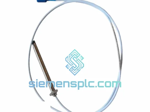
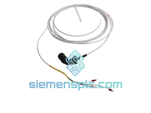
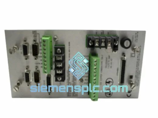
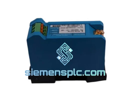
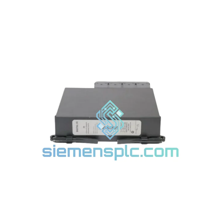
Bently Nevada 991-25-50-01-00 Thrust Transmitter – 3500 Series
3500 Series
Origin US
Thrust Transmitter
Request verified availability, condition, replacement risk review, packing options and courier lead time for 991-05-50-01-00.
Click Request Quote and the part number is inserted into the inquiry form automatically.
Core fields for model confirmation and RFQ routing. Detailed product narrative remains below.
Thrust bearing failure doesn’t announce itself. One shift your vibration panel is clean; the next, you’re looking at a tripped compressor, a locked-out turbine, and a maintenance crew scrambling for a part that your regional distributor quotes at 6–8 weeks. That gap is exactly where we operate. The Bently Nevada 991-05-50-01-00 axial position transmitter is on our shelf in Xiamen right now — verified, tested, and ready to move via DHL or FedEx within 24 hours of order confirmation.
We’ve handled enough emergency callouts to know that when axial position monitoring goes down on a 3500 Series rack, the clock starts immediately. Operations won’t accept a bypass for long. Engineering needs a traceable, OEM-spec replacement — not a workaround. This is that replacement.
⚡ URGENT REQUIREMENT? Contact: [email protected] | WhatsApp: +86 18359268345
| Parameter | Specification | Status |
|---|---|---|
| Part Number | 991-05-50-01-00 | ✅ Ready to Ship |
| Manufacturer | Bently Nevada (Baker Hughes) | OEM Original |
| Series / Platform | 3500 Series Machinery Protection | — |
| Function | Thrust / Axial Position Transmitter | — |
| Compatible Probe System | 3300 XL 8mm Proximity Probe + Driver | — |
| Output Signal | 4–20 mA, loop-powered | — |
| Supply Voltage | 24 VDC nominal | — |
| Isolation | Galvanic, input-to-output | — |
| Operating Temperature | −40 °C to +85 °C | — |
| Compliance | API 670, CE | — |
| Mounting | DIN-rail / panel-mount | — |
| Weight | 290 g | — |
| Country of Origin | United States | — |
| Shipping Origin | Xiamen, China | DHL / FedEx Express |
After handling dozens of 3500 Series field replacements, these are the failure patterns and swap pitfalls that actually matter on site:
Common Fault Signatures Before Failure
Replacement Procedure — Field Checklist
Firmware / Compatibility Note: The 991-05-50-01-00 has no embedded firmware. It is a hardware-only signal conditioning device. There is no firmware version to match, no configuration software required, and no communication protocol to configure. It is compatible with any 3500 Series rack revision and any DCS/PLC analog input accepting 4–20 mA.
The environments where axial position monitoring matters most are exactly the environments that destroy marginal instrumentation. Turbine decks run hot — ambient temperatures above 60 °C are routine near bearing housings. Compressor trains generate broadband vibration that fatigues solder joints and loosens terminal connections over 18–24 month cycles. Coastal and offshore installations add salt-laden humidity that attacks unprotected PCB surfaces within a single wet season.
The 991-05-50-01-00 is rated for continuous operation from −40 °C to +85 °C. The internal PCB uses conformal coating on signal-path components, providing resistance to condensation and airborne contaminants. The DIN-rail housing is designed to maintain terminal clamping force under thermal cycling — a detail that matters when your installation sees 40 °C swings between day and night shifts.
Galvanic isolation between the probe input and the 4–20 mA loop is not just a specification checkbox — it is the feature that keeps a ground fault on the field side from propagating into your DCS analog input card. In petrochemical and power generation environments where ground potential differences between equipment can reach several volts, this isolation is what separates a nuisance alarm from a control system card replacement.
Units supplied from our Xiamen stock are stored in climate-controlled conditions and inspected prior to shipment. We do not ship units that show evidence of prior installation, terminal damage, or label defacement. If a unit arrives and does not meet your incoming inspection criteria, we replace it — no extended RMA process.
Our dispatch hub is in Xiamen, Fujian — one of China’s primary export ports with direct DHL and FedEx service connections to major industrial hubs worldwide. Here is how a typical emergency order moves:
If your plant is in a location where standard express carriers have delivery restrictions, contact us before ordering. We have handled shipments to remote LNG terminals, island installations, and sanctioned-adjacent regions — we know which carriers work and which documentation is required.
📧 Email: [email protected]
💬 WhatsApp: +86 18359268345
🌐 Web: siemensplc.com
© 2026 siemensplc.com. All rights reserved.
We check the full part number, brand, series and visible nameplate information before quotation.
Sales confirms stock path, condition option, quantity and realistic lead time for export dispatch.
DHL, FedEx, UPS or buyer courier arrangements can be reviewed with packing requirements.
Similar brand or category products for fast comparison and multi-item RFQ lists.