BOSCH Rexroth
RFQ Ready
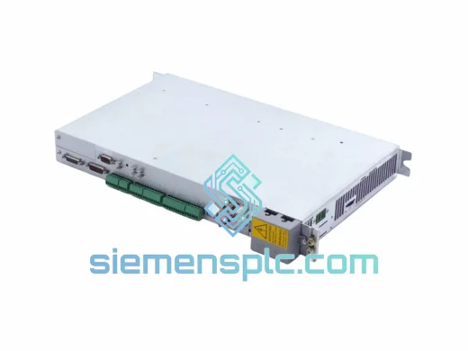
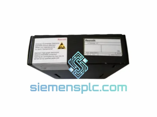
Rexroth VT5035-17 Proportional Amplifier Card – VT5035 Series
VT5035 Series
Origin DE
Proportional Amplifier Card
Request verified availability, condition, replacement risk review, packing options and courier lead time for DEA-4.2.
Click Request Quote and the part number is inserted into the inquiry form automatically.
Core fields for model confirmation and RFQ routing. Detailed product narrative remains below.
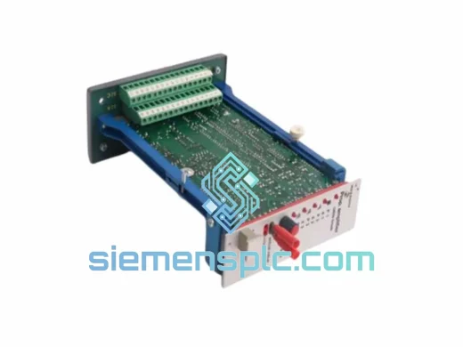
The Bosch Rexroth DEA-4.2 is a dedicated drive interface and axis enable control card engineered for the Indramat TDM, KDS, and RAC series AC servo and spindle drive platforms. Within a closed-loop motion control architecture, the DEA-4.2 occupies the command arbitration layer between the CNC or PLC controller and the power drive stage. It decodes axis enable signals, manages drive-ready handshaking, and routes fault relay logic — functions that are prerequisite to any deterministic torque or velocity command execution.
Unlike generic I/O expansion boards, the DEA-4.2 is purpose-built for Indramat’s drive communication protocol. Its onboard logic handles the enable/disable sequencing that prevents uncontrolled axis movement during power-up, E-stop events, and fault recovery cycles. In multi-axis installations, this sequencing is critical: an improperly timed enable signal can trigger drive overcurrent faults or mechanical shock in gantry and synchronous axis configurations.
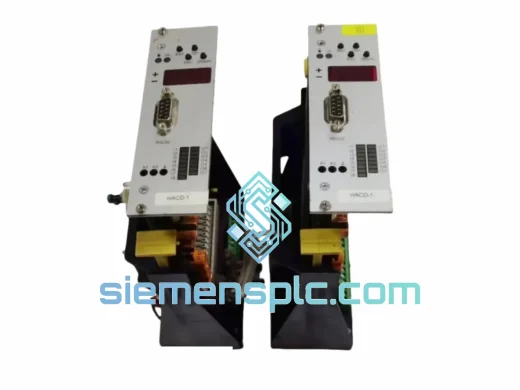
The card interfaces directly with the Indramat drive’s X4 or equivalent control connector, carrying enable, ready, fault, and reference signals on a defined pin assignment. Signal levels are TTL-compatible with internal pull-up/pull-down resistors that maintain defined logic states during cable disconnection — a design choice that prevents spurious enable conditions in the event of wiring faults.
Real-time Stock & RFQ: [email protected] | WhatsApp: +86 18359268345
| Parameter | Specification |
|---|---|
| Part Number / SKU | DEA-4.2 |
| Brand | Bosch Rexroth / Indramat |
| Series | Indramat DEA Series |
| Product Type | Drive Interface / Axis Enable Control Card |
| Supply Voltage (Logic) | +5 VDC (internal bus supply from drive backplane) |
| Signal Interface | TTL-compatible, 24 VDC enable input (optocoupler isolated) |
| Enable Input Voltage | 18–30 VDC (nominal 24 VDC) |
| Relay Output (Drive Ready) | Dry contact, max 30 VDC / 1 A |
| Fault Output | Open collector, active-low, 50 mA sink |
| Operating Temperature | 0 °C to +55 °C |
| Storage Temperature | -25 °C to +70 °C |
| Humidity (Operating) | 5–95% RH, non-condensing |
| PCB Form Factor | Plug-in card, Indramat drive slot compatible |
| Compatible Drive Families | Indramat TDM, KDS, RAC, DIAX04 series |
| Weight | Approx. 200 g |
| Country of Origin | Germany |
| Warranty | 12 months from date of shipment |
The DEA-4.2’s circuit architecture reflects Indramat’s design philosophy of separating control-plane logic from power-plane switching — a principle that directly reduces the risk of control signal corruption during high-current switching transients on the DC bus.
Optocoupler Isolation on Enable Path: The 24 VDC axis enable input is routed through a high-speed optocoupler (typical propagation delay <5 µs) before reaching the drive’s internal enable latch. This galvanic isolation barrier prevents ground potential differences between the PLC output card and the drive chassis from inducing false enable pulses — a failure mode commonly observed in installations where the PLC and drive share a common ground rail with long cable runs.
Defined Fail-Safe Logic States: Internal pull-down resistors on the enable input ensure that an open-circuit condition (broken cable, disconnected connector) defaults to the drive-disabled state. This is a hardware-enforced fail-safe: the drive cannot be inadvertently enabled by a floating signal line. The fault output similarly defaults to the fault-asserted state on power loss, ensuring upstream controllers receive a valid fault indication even during drive power-down sequences.
Drive-Ready Relay Sequencing: The dry-contact relay output that signals drive-ready status is controlled by the drive’s internal watchdog logic, not by the DEA-4.2 card alone. The card routes this signal to the external connector, but the relay coil is energized only after the drive’s internal self-test sequence completes — including DC bus voltage verification, IGBT gate driver self-check, and encoder feedback signal validation. This multi-condition AND logic prevents premature ready signaling.
EMC Design Considerations: The card’s PCB layout routes high-frequency signal traces away from the relay switching circuits. Relay coil suppression diodes are fitted on-board to clamp the inductive kickback voltage during relay de-energization, preventing conducted EMI from coupling into adjacent signal traces. The card’s ground plane is connected to the drive chassis at a single point, avoiding ground loop formation within the card itself.
Connector Retention Mechanism: The edge connector interface uses a friction-lock design with defined insertion force specifications. This prevents partial insertion — a common field failure mode where vibration causes intermittent contact on improperly seated cards, producing transient fault signals that are difficult to diagnose without physical inspection.
Every DEA-4.2 unit supplied by siemensplc.com is sourced as a genuine Bosch Rexroth / Indramat OEM component. Units are not rebranded, cloned, or reverse-engineered. Each card carries the original Indramat part label with serial number and date code, providing full traceability to the manufacturing batch.
Incoming Inspection Protocol: Upon receipt at our Xiamen facility, each card undergoes visual inspection for PCB damage, component integrity, and label authenticity. Cards with evidence of rework, burnt components, or label tampering are quarantined and not offered for sale.
Functional Pre-Shipment Verification: Where test fixtures are available, cards are powered and signal-verified before dispatch. Test results are documented and available upon request.
Packaging: Cards are shipped in anti-static (ESD) bags placed inside rigid foam-lined cartons. The packaging meets ISTA 2A transit test requirements for international air freight. Each shipment includes a packing list with part number, serial number, and condition declaration.
Warranty: 12 months from the date of shipment. Warranty covers manufacturing defects and functional failure under normal operating conditions. Physical damage caused by incorrect installation or overvoltage is excluded.
Logistics from Xiamen, China: Orders are dispatched via DHL Express, FedEx International Priority, or UPS Worldwide Expedited. Standard transit times are 3–5 business days to Europe and North America, 2–4 business days to Southeast Asia. Full tracking numbers and commercial export documentation (commercial invoice, packing list, HS code 8537.10) are provided with every shipment. Customs clearance support is available for buyers in regulated import markets.
Email: [email protected]
WhatsApp: +86 18359268345
Web: siemensplc.com
Location: Xiamen, China
© 2026 siemensplc.com. All rights reserved.
We check the full part number, brand, series and visible nameplate information before quotation.
Sales confirms stock path, condition option, quantity and realistic lead time for export dispatch.
DHL, FedEx, UPS or buyer courier arrangements can be reviewed with packing requirements.
Similar brand or category products for fast comparison and multi-item RFQ lists.