BOSCH Rexroth
RFQ Ready
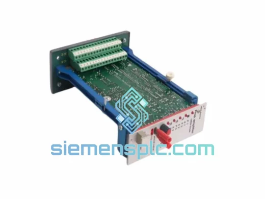
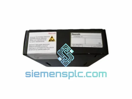
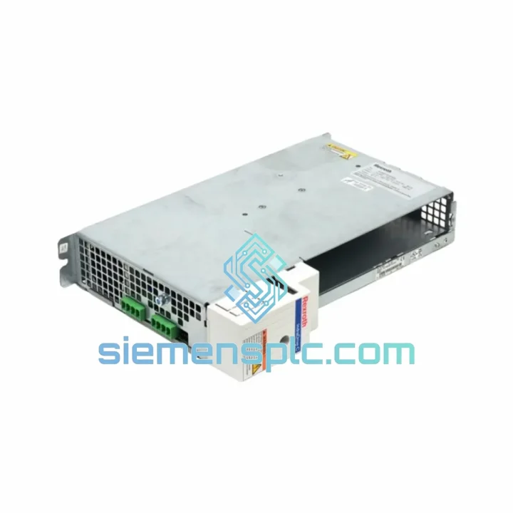
Rexroth VT5035-17 Proportional Amplifier Card – VT5035 Series
VT5035 Series
Origin DE
Proportional Amplifier Card
Request verified availability, condition, replacement risk review, packing options and courier lead time for 1N-W0012-A-07-NNNN.
Click Request Quote and the part number is inserted into the inquiry form automatically.
Core fields for model confirmation and RFQ routing. Detailed product narrative remains below.
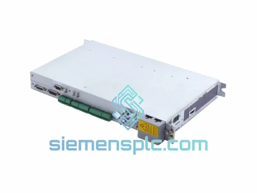
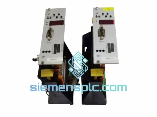
The Bosch Rexroth HMD01.1N-W0012-A-07-NNNN is a double-axis servo inverter module belonging to the IndraDrive Compact (HMD) product line — a drive family engineered for high-density axis packaging within modular cabinet systems. Unlike single-axis inverters, this unit integrates two fully independent servo channels into a 50 mm-wide housing, each rated at 12 A continuous output current (24 A peak for ≤400 ms), powered from a shared 3-phase 400–480 V AC mains input and a common DC bus operating between 540 and 750 V DC.
Within a servo control loop, the HMD01.1N-W0012-A-07-NNNN sits at the innermost execution layer. The motion controller — typically a Rexroth IndraMotion MTX or a third-party CNC — transmits position or velocity setpoints to the drive via a SERCOS II fiber-optic ring. The drive’s onboard DSP resolves these setpoints into d-q axis current commands, executes Field-Oriented Control (FOC) at a fixed 62.5 µs current regulation cycle, and drives the IGBT output stage accordingly. Actual-value feedback (encoder position, actual current) is returned to the controller within the same SERCOS telegram cycle, closing the position loop with bounded, deterministic latency. This architecture is the technical basis for the module’s suitability in multi-axis contouring, electronic gearing, and cam-profile applications where inter-axis phase error must remain within ±1 encoder count at all commanded speeds.
The -A-07 option code in the part number designates the SERCOS II communication interface with analog override input. SERCOS II operates over plastic optical fiber (POF) at 2, 4, or 8 Mbit/s, with selectable cycle times of 1, 2, or 4 ms. The analog override channel (0–10 V or ±10 V) allows feed-rate override from a hardware potentiometer without consuming a SERCOS parameter slot — a practical feature retained from DIAX04-era machine designs that this module is backward-compatible with.
Real-time Stock & RFQ: [email protected] | WhatsApp: +86 18359268345
| Parameter | Value |
|---|---|
| Part Number | HMD01.1N-W0012-A-07-NNNN |
| Drive Family | IndraDrive Compact (HMD) |
| Number of Axes | 2 (fully independent) |
| Continuous Output Current (per axis) | 12 A RMS |
| Peak Output Current (per axis) | 24 A (200% for ≤400 ms) |
| Mains Supply | 3 × 400–480 V AC ±10%, 50/60 Hz |
| DC Bus Voltage | 540–750 V DC (shared) |
| Current Regulation Cycle | 62.5 µs (fixed) |
| Communication Interface | SERCOS II fiber-optic (POF), 2/4/8 Mbit/s |
| SERCOS Cycle Time Options | 1 ms / 2 ms / 4 ms |
| Analog Override Input | 0–10 V / ±10 V (option -A-07) |
| Supported Feedback Systems | Resolver, EnDat 2.1, Hiperface, TTL/HTL incremental encoder |
| IGBT Switching Frequency | 4 kHz |
| Cooling | Forced air, integrated axial fan, rear exhaust |
| Protection Rating | IP20 (IEC 60529) |
| Operating Temperature | 0 °C to +45 °C (derate above 40 °C) |
| Storage Temperature | −25 °C to +70 °C |
| Relative Humidity | 5–95%, non-condensing |
| Vibration (IEC 60068-2-6) | 10–57 Hz / 0.075 mm; 57–150 Hz / 1 g |
| Shock (IEC 60068-2-27) | 15 g / 11 ms half-sine |
| Housing Width | 50 mm (single slot) |
| Unit Weight | 5.6 kg |
| Manufacturer | Bosch Rexroth AG |
| Country of Origin | Germany |
| Warranty | 12 months from dispatch date |
Three-Layer Internal Processing Architecture
The HMD01.1N-W0012-A-07-NNNN partitions its internal processing into three distinct hardware layers: the SERCOS communication processor, the dual-channel DSP current regulator, and the IGBT gate-drive stage. The SERCOS processor handles ring synchronization, telegram parsing, and parameter object management (S-0-xxxx / P-0-xxxx IDN space) independently of the current regulation DSP. This separation ensures that a SERCOS communication fault (e.g., ring break) triggers a defined fault response — controlled deceleration to standstill — rather than an uncontrolled torque transient caused by a regulation loop interruption.
Dual-Channel FOC with Independent Fault Isolation
Each of the two servo channels operates a separate Field-Oriented Control thread on the shared DSP, with independent current sensor inputs (Hall-effect transducers, ±0.5% linearity), independent IGBT half-bridge drivers, and independent fault latch registers. A hardware interlock prevents a fault condition on one channel from asserting the gate-disable signal on the other. When Channel 2 trips on overcurrent, Channel 1 continues closed-loop regulation while the drive firmware logs the fault event with a 62.5 µs timestamp. The machine controller reads the per-channel fault status via SERCOS IDN S-0-0011 and executes a channel-selective stop sequence — a capability that reduces unplanned downtime in dual-axis gantry and tandem-drive configurations.
Shared DC Bus and Regenerative Energy Exchange
Both axes share a common DC bus capacitor bank. During coordinated motion profiles where one axis decelerates while the other accelerates, the regenerated kinetic energy from the braking axis charges the bus capacitors and is drawn directly by the motoring axis without passing through the mains supply module. In typical pick-and-place or reciprocating-axis profiles, this intra-bus energy exchange reduces peak mains demand by 20–35%, allowing the supply module to be sized for average rather than peak power. The DC bus voltage is monitored at 1 ms intervals; if bus voltage exceeds 780 V DC (overvoltage threshold), the firmware activates the braking chopper output to dissipate excess energy through an external braking resistor.
EMC Architecture: Conducted and Radiated Emission Control
The gate-drive PCB uses a split ground plane topology: the high-frequency switching node (IGBT collector/emitter) is referenced to a dedicated power ground island, while all analog feedback signal traces are routed on a separate signal ground plane connected to power ground at a single star point. Ferrite bead arrays (impedance 600 Ω at 100 MHz) are placed on all resolver excitation and feedback lines. The IGBT switching frequency of 4 kHz places the fundamental switching harmonic above the 2 kHz upper boundary of IEC 61000-4-8 power-frequency magnetic field immunity tests, while remaining within the thermal dissipation budget of the forced-air cooling system. The module meets IEC 61800-3 Category C2 conducted emission limits with Rexroth IKL/IKS shielded motor cables terminated at both ends — no external EMC filter required in standard installations.
Resolver and EnDat 2.1 Signal Conditioning
The resolver interface generates an 8 kHz, 7 V RMS sinusoidal excitation signal and processes the returned sine/cosine signals through a tracking resolver-to-digital converter (RDC) with 16-bit angular resolution (0.0055°/LSB). The EnDat 2.1 interface supports absolute position readout at power-on, eliminating reference-point homing cycles for absolute encoders. All feedback signal lines pass through differential line receivers with ±15 kV ESD protection diodes and 120 Ω termination resistors, maintaining signal integrity on motor cable runs up to 50 m without signal conditioning repeaters.
Each HMD01.1N-W0012-A-07-NNNN unit shipped from our Xiamen, China facility is a genuine Bosch Rexroth component procured through verified industrial supply channels. Pre-shipment inspection covers four mandatory checkpoints:
Transit times from Xiamen port: Europe (Frankfurt, Rotterdam) 5–7 business days via air freight; North America (Los Angeles, Chicago) 4–6 business days; Southeast Asia 2–3 business days. Complete export documentation — commercial invoice, packing list, certificate of origin, and HS code 8537.10 classification — is included with every shipment. DDP (Delivered Duty Paid) terms are available on request for EU and US consignees.
Email: [email protected]
WhatsApp: +86 18359268345
Web: siemensplc.com
Location: Xiamen, China
© 2026 siemensplc.com. All rights reserved.
We check the full part number, brand, series and visible nameplate information before quotation.
Sales confirms stock path, condition option, quantity and realistic lead time for export dispatch.
DHL, FedEx, UPS or buyer courier arrangements can be reviewed with packing requirements.
Similar brand or category products for fast comparison and multi-item RFQ lists.