Fuji Electric
RFQ Ready
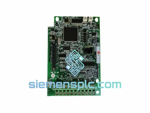
FUJI Electric EP-3531D C1-Z1 Inverter Control Board
P-3531D C1-Z1 FRENIC Series
Origin Japan
Inverter Drive Control Board
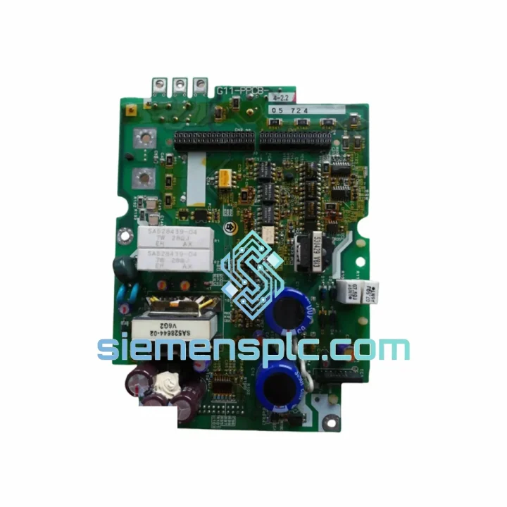
Request verified availability, condition, replacement risk review, packing options and courier lead time for G11-PPCB-4-2.
Click Request Quote and the part number is inserted into the inquiry form automatically.
Core fields for model confirmation and RFQ routing. Detailed product narrative remains below.
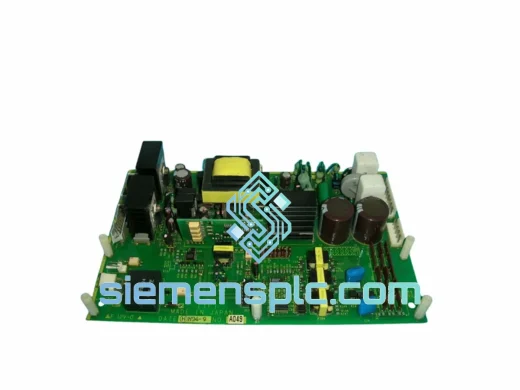
The G11-PPCB-4-2.2 SA528530-06 is the dedicated power printed circuit board for the FUJI Frenic-G11 series, specifically matched to the 4-pole, 2.2 kW drive configuration. Within the Frenic-G11 architecture, this board occupies the critical interface layer between the microprocessor-based control section and the IGBT power conversion stage. It carries gate drive signals, DC bus voltage sensing lines, thermistor feedback paths, and overcurrent protection logic — all of which must operate with sub-microsecond timing accuracy to maintain stable PWM output and protect the power module from destructive fault conditions.
When this board degrades — through capacitor aging, solder joint fatigue under thermal cycling, or gate resistor drift — the drive exhibits symptoms ranging from erratic output frequency to hard overcurrent trips (OC1/OC2) and ground fault alarms. Replacing the board with a genuine SA528530-06 assembly restores the original gate drive impedance, protection threshold calibration, and signal integrity that the Frenic-G11 platform was designed around.
Real-time Stock & RFQ: [email protected] | WhatsApp: +86 18359268345
| Parameter | Specification |
|---|---|
| Part Number | G11-PPCB-4-2.2 SA528530-06 |
| Manufacturer | FUJI Electric Co., Ltd. |
| Compatible Series | Frenic-G11 (FRN-G11 Series) |
| Board Classification | Power PCB — Gate Drive & Protection Interface |
| Drive Power Class | 2.2 kW (3 HP) |
| Pole Configuration | 4-pole (400 V class, 3-phase input) |
| DC Bus Voltage Range | Approx. 560–620 V DC (nominal 400 V AC input) |
| Gate Drive Output | Isolated gate signals for 6-pulse IGBT bridge |
| Isolation Method | Photocoupler-based galvanic isolation per gate channel |
| Overcurrent Detection | Shunt-based current sensing with hardware latch |
| Thermistor Input | NTC thermistor interface for heatsink thermal monitoring |
| PCB Substrate | FR-4 glass-epoxy, 1.6 mm, multi-layer |
| Operating Temperature | −10 °C to +50 °C (ambient, drive enclosure) |
| Weight | 4,460 g (assembled with mounting hardware) |
| Warranty | 12 months from date of shipment |
| Condition | New OEM / Tested Refurbished (specify at RFQ) |
The SA528530-06 board implements a six-channel isolated gate drive topology, with each IGBT gate channel driven through a dedicated photocoupler stage. This architecture ensures that the high-voltage power section (DC bus at 560–620 V) is fully galvanically isolated from the 5 V logic domain of the control PCB. The isolation barrier sustains a minimum of 2,500 V AC (1 minute) per channel, which is essential in 400 V class drives where common-mode transients during switching events can reach several hundred volts in microseconds.
Gate resistor values on this board are matched to the specific IGBT module used in the 2.2 kW Frenic-G11 chassis. The turn-on resistor (Rg_on) and turn-off resistor (Rg_off) are selected to balance switching loss against dV/dt-induced overvoltage across the collector-emitter junction. Deviation from these values — as occurs with counterfeit or mismatched replacement boards — results in either excessive switching losses (thermal runaway risk) or voltage spikes that exceed the IGBT’s rated VCES, causing latent damage or immediate module failure.
The overcurrent protection circuit uses a low-inductance shunt resistor in the DC bus path. The sensed voltage is fed into a fast comparator with a hardware latch: once the overcurrent threshold is crossed, the gate signals are blanked within approximately 2–3 µs, independent of the control CPU. This hardware-level response time is critical because software-based protection in the DSP cannot react fast enough to prevent IGBT destruction under hard short-circuit conditions.
EMC performance on the SA528530-06 is achieved through a combination of decoupling capacitors placed at each gate drive IC supply pin, ferrite bead filtering on signal lines crossing the isolation boundary, and a ground plane layout that minimizes high-frequency loop areas. The board layout follows FUJI Electric’s internal EMC design rules, which are aligned with IEC 61800-3 Category C2 conducted and radiated emission limits for variable speed drives.
The thermistor interface circuit conditions the NTC resistance signal into a voltage proportional to heatsink temperature, which the control PCB samples via its ADC. The conditioning network includes a linearization resistor and a low-pass RC filter (cutoff approximately 10 Hz) to reject switching noise from the ADC input. This ensures accurate thermal monitoring without false over-temperature trips caused by PWM-frequency interference.
Each G11-PPCB-4-2.2 SA528530-06 unit supplied by siemensplc.com is sourced through verified industrial component channels and undergoes a structured inspection process before dispatch. Visual examination covers solder joint integrity, component seating, PCB surface condition, and connector pin alignment. Functional verification — where applicable — is performed in a compatible Frenic-G11 drive chassis to confirm gate drive output waveforms and protection circuit response.
All boards are packaged in anti-static (ESD) shielding bags, placed in foam-lined cartons, and sealed for transit. Shipments originate from our warehouse in Xiamen, China, and are dispatched via DHL Express, FedEx International Priority, or UPS Worldwide, with full tracking provided at the time of shipment. For bulk orders, sea freight consolidation via Xiamen Port is available with competitive transit times to major global ports.
Xiamen’s position as a major southern China logistics hub provides direct access to international air freight routes and container shipping lanes, enabling consistent 3–7 business day delivery to most destinations in Southeast Asia, the Middle East, Europe, and the Americas. Export documentation — including commercial invoice, packing list, and certificate of origin — is prepared in compliance with destination country import requirements.
A 12-month warranty is provided on all units from the date of shipment. Warranty coverage addresses manufacturing defects and component failures under normal operating conditions as defined in the Frenic-G11 installation manual. Warranty claims are processed with a replacement-first policy to minimize customer downtime.
Email: [email protected]
WhatsApp: +86 18359268345
Web: siemensplc.com
Location: Xiamen, China
© 2026 siemensplc.com. All rights reserved.
We check the full part number, brand, series and visible nameplate information before quotation.
Sales confirms stock path, condition option, quantity and realistic lead time for export dispatch.
DHL, FedEx, UPS or buyer courier arrangements can be reviewed with packing requirements.
Similar brand or category products for fast comparison and multi-item RFQ lists.