GE
RFQ Ready
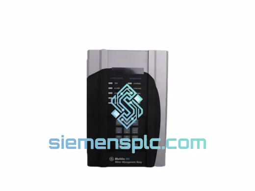
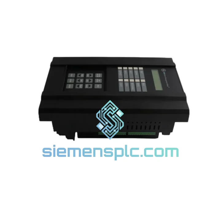
GE UR7BH Communication Module
GE UR7BH Multilin UR Series
Origin US
Communication Module
Request verified availability, condition, replacement risk review, packing options and courier lead time for 369-HI-R-M-0-0.
Click Request Quote and the part number is inserted into the inquiry form automatically.
Core fields for model confirmation and RFQ routing. Detailed product narrative remains below.
The GE Multilin 369-HI-R-M-0-0 occupies a well-defined position in the motor protection hierarchy: it sits between the power distribution bus and the motor terminal, executing protection logic with sub-cycle response times while simultaneously feeding structured diagnostic data upstream to SCADA and DCS layers. Unlike discrete relay assemblies that require external wiring to aggregate protection functions, the 369-HI-R-M-0-0 consolidates thermal overload, ground fault, phase unbalance, undercurrent, stall/jam detection, and RTD-based temperature monitoring into a single 4U panel-mount chassis. This architectural consolidation directly reduces wiring complexity, eliminates inter-relay timing dependencies, and provides a single point of truth for motor health data.
The relay is designed for AC induction motors operating in medium-voltage and low-voltage switchgear environments. Its current sensing architecture accepts inputs from external current transformers across a wide CT secondary range, making it compatible with motor FLA ratings from fractional amperes to several thousand amperes without hardware modification — only setpoint adjustment. The high-impedance input (HI suffix) variant is specifically configured for applications where the CT secondary burden must remain minimal to preserve measurement accuracy across long cable runs, a common constraint in offshore platforms, mining headframes, and large process plant motor control centers.
Real-time Stock & RFQ: [email protected] | WhatsApp: +86 18359268345
| Parameter | Specification |
|---|---|
| Model | 369-HI-R-M-0-0 |
| Manufacturer | General Electric (GE Multilin) |
| Series | 369 Motor Management Relay |
| Input Configuration | High-impedance CT input (HI variant) |
| Output Type | Relay output contacts (R variant) |
| Communication Protocol | Modbus RTU over RS-485 (M variant) |
| Optional Add-on Modules | None (0-0 suffix) |
| Protection Functions | Thermal overload (49), phase unbalance (46), undercurrent (37), overcurrent (50/51), ground fault (50G/51G), stall/jam (48/51LR), starts-per-hour (66), RTD thermal (38/49T) |
| RTD Inputs | Up to 12 channels (PT100 / Ni120 compatible) |
| Metering | Phase currents, ground current, thermal capacity used (TCU%), motor run hours, number of starts |
| Display | Backlit LCD with multi-LED status annunciation |
| Mounting | Panel-mount, flush or surface; DIN-rail adapter available |
| Standards | ANSI/IEEE C37.96, IEC 60255 motor protection standards |
| Operating Temperature | -20°C to +60°C |
| Weight | Approx. 3,520 g |
| Warranty | 12 months from date of shipment |
CT Input Architecture and Burden Management: The HI-suffix designation indicates a high-impedance current input stage. In practice, this means the relay presents a burden of less than 0.1 VA per phase at rated current — a critical parameter when the CT secondary cable run exceeds 50 meters. Excessive burden causes CT saturation under fault conditions, which compresses the secondary current waveform and introduces measurement error precisely when accuracy is most critical. The 369-HI-R-M-0-0 eliminates this failure mode by maintaining a near-zero burden across its full operating range.
Thermal Model Accuracy: The relay implements a dual-element thermal model that tracks both positive-sequence heating (I²t accumulation) and negative-sequence heating (which generates approximately six times the rotor losses of equivalent positive-sequence current). The thermal capacity used (TCU%) register is continuously updated at the relay’s internal scan rate and is accessible via Modbus register map without polling latency. This allows SCADA systems to implement predictive maintenance logic based on real thermal state rather than estimated values derived from nameplate data alone.
EMC Design and Isolation: The relay’s analog input stage employs optical isolation between the CT secondary circuit and the relay’s internal logic bus. This galvanic barrier prevents ground loop currents — common in large motor control centers where multiple ground reference potentials exist — from injecting noise into the measurement chain. The relay meets IEC 61000-4-5 surge immunity requirements at 4 kV line-to-earth, which is the relevant test level for switchgear-mounted protection devices exposed to switching transients from adjacent contactors and circuit breakers.
Relay Output Contact Architecture: The R-suffix output stage uses electromechanical relay contacts rated for 8A at 250 VAC. Each output is independently assignable to any protection element or combination of elements via the setpoint matrix. The trip output contact is configured as normally energized (fail-safe) by default, meaning a loss of relay auxiliary power results in a trip signal — the correct fail-safe behavior for motor protection applications where an unpowered relay must not allow an unprotected motor to continue running.
Modbus RTU Implementation: The M-suffix communication module implements Modbus RTU over RS-485 at configurable baud rates from 1200 to 19200 bps. The relay’s register map exposes all metering values, protection setpoints, event log entries, and relay output states as standard 16-bit holding registers. The event log stores the 64 most recent protection events with timestamp, pre-fault current values, and fault type code — sufficient for post-incident analysis without requiring a dedicated data recorder.
Every GE 369-HI-R-M-0-0 unit supplied by siemensplc.com is sourced through verified channels with full traceability to authorized GE Multilin distribution. Units are inspected upon receipt for label integrity, firmware version consistency, and physical condition. Where test equipment is available, functional verification of communication and output contacts is performed prior to shipment.
Shipments originate from our warehouse in Xiamen, China — a major logistics hub with direct access to international freight forwarding services via Xiamen Gaoqi International Airport and Xiamen Port. Standard export documentation includes commercial invoice, packing list, and certificate of conformance. DHL Express, FedEx International Priority, and sea freight consolidation are available depending on order volume and delivery urgency.
Transit times to major destinations: Europe 3–5 business days (air), Southeast Asia 2–3 business days (air), North America 4–6 business days (air). All units ship with ESD-protective inner packaging and shock-absorbing outer cartons. A 12-month warranty covers manufacturing defects and functional failures under normal operating conditions from the date of shipment.
Email: [email protected]
WhatsApp: +86 18359268345
Web: siemensplc.com
Location: Xiamen, China
© 2026 siemensplc.com. All rights reserved.
We check the full part number, brand, series and visible nameplate information before quotation.
Sales confirms stock path, condition option, quantity and realistic lead time for export dispatch.
DHL, FedEx, UPS or buyer courier arrangements can be reviewed with packing requirements.
Similar brand or category products for fast comparison and multi-item RFQ lists.