GE
In Stock OK
GE DS200SDCCGSAHD DCS I/O Module – Mark VI
Request verified availability, condition, replacement risk review, packing options and courier lead time for DS200SDCCGSAHD.
BrandGE
Part NumberDS200SDCCGSAHD
ConditionAvailability Check
Lead TimeRFQ Confirmation
DocumentsDatasheet / photos by RFQ
ShippingExport packing available
Auto-filled RFQ
DS200SDCCGSAHD
Click Request Quote and the part number is inserted into the inquiry form automatically.
- Reply by email: [email protected]
- WhatsApp / Tel: +86 18359268345
- Mon-Sat 9:00-18:00 GMT+8
Procurement Data
Key Product Information
Core fields for model confirmation and RFQ routing. Detailed product narrative remains below.
- Brand
- GE
- Primary Part Number
- DS200SDCCGSAHD
- Product Type
- DCS I/O Module
- Series / Family
- Mark VI
- Manufacturer
- General Electric (GE)
- Country of Origin
- US
- Catalog Category
- I/O Modules
- Operating Temp.
- 0 °C to +60 °C (standard industrial control cabinet)
- Warranty
- 12 months functional guarantee from date of shipment
Model confirmed for inquiry
DS200SDCCGSAHD
Send quantity, destination and urgency. The RFQ form keeps this part number attached.
Request Quote
Product Overview
DS200SDCCGSAHD: Discrete Channel Signal Conditioning at the Mark VI Protection Boundary
The DS200SDCCGSAHD is a discrete-channel signal conditioning and I/O interface board produced by General Electric for the Mark VI and Mark VIe turbine control platforms. Its functional position within the control architecture is precise: it occupies the electrical boundary between field-level discrete devices and the controller’s internal logic domain, performing the conditioning, isolation, and scan-synchronous transfer of discrete state information across that boundary without introducing variable latency into the protection execution cycle.
Field devices interfaced through this board span the full range of discrete instrumentation found in gas and steam turbine installations — dry-contact limit switches on valve actuators, proximity sensors on rotating components, solenoid valve position feedback contacts, relay coil drivers for ESD sequences, and annunciator panel output drivers. The board does not perform analog-to-digital conversion; its function is strictly discrete: it maps the binary state of field contacts to logic-level register bits on the Mark VI backplane bus, and maps backplane output register bits to energized or de-energized field output channels.
The architectural constraint that governs the DS200SDCCGSAHD’s design is the Mark VI’s fixed scan period structure. Protection-class functions execute on a 10 ms scan period; supervisory-class functions execute on a 40 ms period. Any I/O board that fails to complete its input sampling and output assertion within a single backplane arbitration window would force a scan period extension across the entire rack — an outcome that is architecturally prohibited in a turbine protection system. The DS200SDCCGSAHD achieves scan-synchronous operation through register-mapped I/O: input channel states are written to a fixed memory-mapped address block on the VME-derived backplane bus at the start of each scan, and output channel commands are read from a corresponding address block at the end of each scan. The bus transaction completes within one arbitration cycle, contributing no measurable jitter to the overall scan cycle timing.
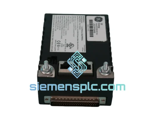
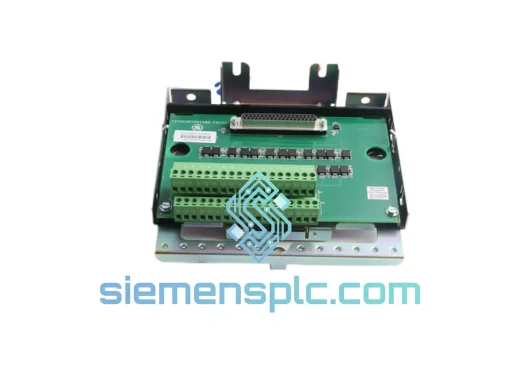
Physical installation follows GE’s terminal board separation architecture. Field wiring terminates on a dedicated terminal board — typically the TBCI (Terminal Board for Contact Inputs) or TBQC (Terminal Board for Quick Connect) — mounted separately within the control cabinet. The DS200SDCCGSAHD connects to the terminal board via a short direct-mate or ribbon interconnect. This two-layer physical architecture confines field-side wiring transients, ground potential differences, and inductive switching noise to the terminal board layer. Field-side disturbances do not reach the backplane bus, and the DS200SDCCGSAHD’s logic domain operates in a stable electrical environment regardless of the noise conditions present in the field cable tray.
In Triple Modular Redundant (TMR) Mark VI configurations, three DS200SDCCGSAHD boards operate in parallel within separate R, S, and T controller racks. Each board independently samples the same field input signals. The Mark VI controller performs a 2-of-3 majority vote on the digitized input states before passing the result to the protection algorithm. A single board failure — whether from optocoupler degradation, a logic rail fault, or connector intermittency — does not alter the voted input state seen by the turbine protection algorithm. Output channels in TMR configurations are driven by three independent boards simultaneously, with the field device responding to the energized majority. This architecture permits a degraded DS200SDCCGSAHD to be identified, alarmed, and replaced online without interrupting turbine operation, provided the remaining two TMR boards are confirmed healthy.
The board’s diagnostic register map exposes optocoupler health status, output latch state, and backplane communication status — all readable remotely through the Mark VI Toolbox HMI without physical access to the rack. In a TMR installation, a per-channel vote disagreement between boards generates a maintenance alarm in the Toolbox HMI before the fault escalates to a condition where the voted state itself is affected. This fault transparency mechanism gives operations staff a defined maintenance window rather than an unplanned outage.
Real-time Stock & RFQ: [email protected] | WhatsApp: +86 18359268345
Technical Parameters
| Part Number | DS200SDCCGSAHD |
| Manufacturer | General Electric (GE) |
| Series / Platform | Mark VI / Mark VIe Turbine Control System |
| Module Function | Discrete Channel Signal Conditioning & I/O Interface Board |
| Form Factor | PCB card module, card-cage rack insertion, VME-derived slot |
| Backplane Bus Protocol | Register-mapped I/O over VME-derived Mark VI backplane; single arbitration cycle per scan |
| Input Channel Type | Discrete digital inputs — dry/wet contact sensing, 24 VDC nominal field sensing voltage |
| Output Channel Type | Discrete digital outputs — relay coil drive, solenoid valve actuation, annunciator panel drivers |
| Isolation Architecture | Per-channel group optical isolation; galvanic break rated ≥1,500 V field-to-logic |
| Scan Cycle Compatibility | 10 ms protection class / 40 ms supervisory class Mark VI scan periods |
| Redundancy Configurations | Simplex, Dual, or TMR (Triple Modular Redundant) 2-of-3 voted I/O |
| Terminal Board Interface | TBCI / TBQC terminal board family (direct-mate or ribbon interconnect) |
| Compatible Turbine Frames | GE Frame 5, 6, 7, 9 gas turbines; combined-cycle steam turbine configurations |
| Operating Temperature | 0 °C to +60 °C (standard industrial control cabinet) |
| Hazardous Area Classification | Class I, Division 2 (non-incendive) per NEC / IEC 60079-15 |
| Bus Transaction Latency | <1 µs per arbitration cycle (negligible contribution to 10 ms scan budget) |
| Approximate Weight | 360 g |
| Supply Condition | New surplus / tested surplus (specify at RFQ) |
| Warranty | 12 months functional guarantee from date of shipment |
Hardware Logical Analysis
Per-Channel Optocoupler Isolation and Transient Suppression: Each discrete input channel routes through a dedicated optocoupler before entering the board’s CMOS logic domain. The LED side of the optocoupler is driven by the field-side sensing circuit through a current-limiting resistor network; the phototransistor side drives the internal logic rail. The galvanic separation — rated to withstand field-to-logic transients of ≥1,500 V — addresses a specific failure mode endemic to turbine control environments: inductive kickback from solenoid valve de-energization. When a solenoid valve coil is de-energized, the collapsing magnetic field generates a voltage spike that can reach several hundred volts on the field wiring. Without the optocoupler barrier, this spike would couple into the backplane logic rail through the input sensing resistor network, producing a spurious logic-high state and potentially triggering a false turbine trip. The DS200SDCCGSAHD’s per-channel isolation architecture absorbs field-side transients within the optocoupler’s isolation barrier before they can propagate to the controller logic domain.
Scan-Boundary Output Latch Architecture: Output channels are driven by latched registers updated exclusively at the defined scan boundary — the moment the Mark VI controller writes the new output command block to the backplane bus. Between scan boundaries, the latch holds its previous state regardless of any intermediate logic evaluation occurring within the controller. This prevents a class of output glitch failures where a partially evaluated protection algorithm could momentarily assert an incorrect output state during mid-scan computation. In turbine emergency shutdown (ESD) sequences, where a trip solenoid must transition from energized to de-energized in a single deterministic step, the latched output architecture is a fundamental safety requirement. The latch clock is derived from the backplane scan synchronization signal, ensuring all output channels on the board transition simultaneously at the scan boundary with no channel-to-channel skew.
TMR Vote Arbitration and Fault Transparency: In a TMR Mark VI rack, the DS200SDCCGSAHD boards in the R, S, and T controllers each independently digitize the same field input signals. The Mark VI’s vote arbitration logic compares the three digitized states on a per-channel basis. A disagreement on any single channel — where one board reports a different state than the other two — generates a maintenance alarm in the Mark VI Toolbox HMI without affecting the voted output state. This fault transparency mechanism allows maintenance engineers to identify a degraded DS200SDCCGSAHD before the fault escalates to a condition where the voted state itself is affected. The board’s diagnostic register map exposes optocoupler health status, output latch state, and backplane communication status, all readable remotely through the Mark VI Toolbox without physical access to the rack.
EMC Design and Cabinet Noise Environment: The DS200SDCCGSAHD’s PCB layout follows GE’s EMC partitioning guidelines for the Mark VI platform: field-side circuitry and logic-side circuitry are physically separated on the board with a ground plane break at the optocoupler isolation boundary. Decoupling capacitors are placed at each logic IC power pin to suppress high-frequency switching transients on the logic supply rail. The board’s metal faceplate provides a continuous shield connection to the rack chassis ground, reducing radiated susceptibility from adjacent high-current output boards in the same rack. These measures collectively allow the DS200SDCCGSAHD to maintain specified input threshold accuracy and output drive capability in the presence of the conducted and radiated noise levels typical of a gas turbine control enclosure.
System Integration Benefits
- Deterministic Protection Scan Participation: Input sampling and output assertion complete within a single backplane arbitration window (<1 µs), ensuring the DS200SDCCGSAHD contributes zero measurable latency to the 10 ms protection-class scan cycle. Vibration switch contacts, flame detector outputs, and overspeed relay feedback are processed within the same scan cycle as the protection algorithm evaluation.
- Field-Side Transient Containment: Per-channel optical isolation with ≥1,500 V galvanic break rating prevents inductive switching transients from solenoid valves, motor contactors, and relay coils from coupling into the backplane logic rail, directly reducing nuisance trip events attributable to field-side electrical noise in shared cable trays.
- Glitch-Free Output Assertion: Scan-boundary-synchronized output latching eliminates mid-scan output glitches, ensuring trip solenoids and ESD relay coils receive clean, single-transition commands with no intermediate state assertion during protection algorithm evaluation.
- Online Board Replacement Without Turbine Outage: In TMR configurations, a degraded DS200SDCCGSAHD can be extracted and replaced during turbine operation. The remaining two healthy boards maintain the voted I/O state throughout the replacement, eliminating the need for a planned outage solely to replace an I/O board.
- Proactive Fault Detection via Per-Channel Vote Monitoring: The Mark VI’s per-channel vote comparison continuously monitors agreement between all three TMR boards. A single-board disagreement generates a maintenance alarm before the fault affects the voted state, giving operations staff advance warning and a defined maintenance window rather than an unplanned trip.
- Remote Diagnostic Register Access: Board health status — optocoupler integrity, output latch state, backplane communication status — is exposed through the Mark VI diagnostic register map and readable via the Mark VI Toolbox HMI without physical rack access, reducing fault diagnosis time from hours to minutes.
- Zero Field Re-Termination on Replacement: Compatibility with the TBCI and TBQC terminal board family means field wiring remains undisturbed during board replacement. Only the DS200SDCCGSAHD logic board is exchanged; the terminal board and all field wiring stay in place, reducing replacement time to under 15 minutes in a practiced maintenance environment.
- Hazardous Area Cabinet Installation: Class I, Division 2 (non-incendive) rating per NEC and IEC 60079-15 permits installation in control cabinets located in areas where flammable gas concentrations may be present under abnormal conditions, covering the majority of gas turbine enclosure and compressor station environments without requiring additional intrinsic safety barriers on the logic board side.
- Scalable Redundancy Without Hardware Replacement: The DS200SDCCGSAHD supports simplex, dual, and TMR redundancy configurations within the same hardware form factor. A simplex installation can be upgraded to TMR by adding boards and reconfiguring the Mark VI controller software, without replacing the existing board or re-terminating field wiring.
- Broad Frame Compatibility: Validated for use across GE Frame 5, 6, 7, and 9 gas turbine installations as well as combined-cycle steam turbine configurations, allowing a single spare board to cover multiple unit types within a multi-turbine power station inventory.
Quality Assurance & Global Logistics
All DS200SDCCGSAHD units supplied through siemensplc.com are sourced from verified decommissioned OEM installations or documented authorized surplus channels. Each unit passes a structured pre-shipment inspection protocol before dispatch:
- PCB Surface Inspection: Full visual examination for burnt or discolored components, cracked solder joints, electrolytic capacitor bulging, corrosion on connector pins, and physical damage to the board edge connector. Units with any visible anomaly are quarantined and removed from available stock.
- Connector Mating Force and Pin Integrity Check: All backplane edge connectors and field-side interconnect connectors are inspected for bent pins, contamination, and mating force compliance against GE’s connector specification.
- Functional Bench Verification: Where test fixtures are available, boards are powered and discrete I/O channel states are verified against known-good reference patterns. Test records are retained and provided on request.
- Hardware Revision and Serial Number Documentation: PCB revision level, serial number, and firmware version (where readable from on-board EEPROM) are recorded and included in the shipment documentation package.
- ESD and Moisture-Compliant Packaging: Each board is sealed in a conductive anti-static bag, cushioned with conductive foam, and enclosed in a double-wall corrugated carton. Packaging complies with IPC/JEDEC J-STD-033 handling requirements for ESD-sensitive and moisture-sensitive assemblies.
All shipments originate from Xiamen, China. International dispatch is via DHL Express or FedEx International Priority, with typical transit times of 3–5 business days to Europe, North America, the Middle East, and Southeast Asia. Orders confirmed before 14:00 CST are eligible for same-day dispatch. Complete export documentation — commercial invoice, packing list, and Certificate of Origin — is prepared for every international shipment. A 12-month functional warranty covers all units from the date of shipment; RMA processing is initiated within 24 business hours of a warranty claim submission.
Contact Information
Email: [email protected]
WhatsApp: +86 18359268345
Web: siemensplc.com
Location: Xiamen, China
© 2026 siemensplc.com. All rights reserved.
Ready to quote
[email protected]
Send This Part Number to Sales
RFQ workflow
Quality workflow ->
Confirmation Process
01Model confirmation
We check the full part number, brand, series and visible nameplate information before quotation.
02Availability reply
Sales confirms stock path, condition option, quantity and realistic lead time for export dispatch.
03Packing & courier
DHL, FedEx, UPS or buyer courier arrangements can be reviewed with packing requirements.
Continue sourcing
Browse full catalog ->
Related Automation Parts
Similar brand or category products for fast comparison and multi-item RFQ lists.