GE
RFQ Ready
GE UR7BH Communication Module
GE UR7BH Multilin UR Series
Origin US
Communication Module
Request verified availability, condition, replacement risk review, packing options and courier lead time for MTM-120-S-A20-120VA.
Click Request Quote and the part number is inserted into the inquiry form automatically.
Core fields for model confirmation and RFQ routing. Detailed product narrative remains below.
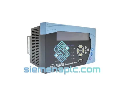
The GE MTM-120(S-A20-120VA) is a panel-mount power metering module designed for continuous electrical parameter acquisition in low-voltage switchgear assemblies, motor control centers (MCCs), and industrial power distribution boards. The S-A20 configuration suffix defines the input burden network topology, matched to a 120 VA rated burden — a value that directly governs the resistive and reactive load the module presents to the current transformer (CT) secondary circuit. Exceeding this burden causes CT saturation, which degrades measurement accuracy and, in protection-grade CTs, can impair relay operation. The 120 VA rating is therefore not a thermal limit alone; it is a system-level constraint that must be factored into the total CT secondary burden calculation alongside the protection relay and wiring resistance.
Within the control loop, the MTM-120(S-A20-120VA) occupies the measurement layer between the CT/VT secondary terminals and the supervisory control system. It converts analog secondary signals into calibrated digital representations of active power (kW), reactive power (kVAR), apparent power (kVA), power factor (PF), line-to-line and line-to-neutral voltage, per-phase current, and accumulated energy (kWh, kVARh). These values are made available to SCADA systems, energy management platforms, and building automation controllers via a serial communication bus — Modbus RTU or DNP3 depending on the firmware variant — at configurable baud rates and polling intervals. The module’s internal sampling architecture captures harmonic content up to the 31st order, providing a continuous power quality baseline at each monitored feeder without requiring a dedicated portable analyzer.
The MTM-120 series is engineered for long-cycle industrial deployments where measurement stability, communication reliability, and low maintenance burden are primary selection criteria. Its non-volatile energy register, galvanically isolated communication port, and bounded Modbus response time make it suitable for integration into both legacy SCADA architectures and modern IIoT data acquisition frameworks.
📦 Real-time Stock & RFQ: [email protected] | WhatsApp: +86 18359268345
| Parameter | Specification |
|---|---|
| Model Number | MTM-120(S-A20-120VA) |
| Manufacturer | General Electric (GE) |
| Series | MTM-120 |
| Configuration Suffix | S-A20 |
| Rated Burden | 120 VA |
| Module Category | Panel-Mount Power Meter Module |
| Measured Quantities | V (L-L, L-N), I (per phase), kW, kVAR, kVA, PF, kWh, kVARh, THD-V, THD-I |
| CT Input Rating | 5 A secondary (standard); verify per installation drawing |
| VT Input Rating | 120 V nominal secondary (typical); confirm per GE MTM-120 datasheet |
| Harmonic Measurement | Up to 31st order (THD-V and THD-I) |
| Communication Protocol | Modbus RTU / DNP3 (firmware-dependent) |
| Communication Interface | RS-485, 2-wire; galvanically isolated |
| Isolation Voltage (Comm) | ≥ 2.5 kV RMS (optocoupler barrier) |
| Dielectric Withstand | 2 kV AC, 1 min (input terminals to chassis) |
| Accuracy Class | Class 0.5 / Class 1 per IEC 62053-22 (confirm with GE datasheet) |
| Modbus Response Time | < 50 ms at 9600 baud (full register block read) |
| Energy Register | Non-volatile EEPROM; > 1,000,000 write cycles endurance |
| Mounting Style | Panel-mount; DIN-rail compatible per enclosure design |
| Operating Temperature | −20 °C to +70 °C |
| Storage Temperature | −40 °C to +85 °C |
| Relative Humidity | 5% to 95% non-condensing |
| Enclosure Rating | IP20 (module body) |
| Power Supply | Derived from VT secondary or auxiliary supply (refer to wiring diagram) |
| Shipping Weight | 7,000 g |
| Country of Origin | United States |
| Warranty | 12 months from date of shipment |
The MTM-120(S-A20-120VA) is built around a simultaneous-sampling multi-channel sigma-delta ADC front end. Unlike sequential-sampling architectures — where voltage and current channels are sampled in rotation — simultaneous sampling eliminates inter-channel phase skew. In a three-phase system, power factor is computed from the phase angle between voltage and current waveforms; a 100 µs sampling offset between channels at 50 Hz introduces a 1.8° phase error, which translates directly into a measurable power factor calculation error. The simultaneous-sampling architecture removes this error source at the hardware level, independent of firmware compensation.
The 120 VA burden specification governs the input impedance of the CT measurement circuit. The S-A20 suffix designates a specific burden network configuration — a combination of precision resistors and reactive elements — that presents the correct load to the CT secondary while maintaining the module’s accuracy class across the full current measurement range. This network is factory-calibrated; field modification is not supported and would invalidate the accuracy class certification.
EMC hardening is implemented at the analog input stage through common-mode chokes on each CT and VT input terminal, combined with transient voltage suppression (TVS) diodes rated for IEC 61000-4-4 fast transient immunity and IEC 61000-4-5 surge immunity. Switchgear environments generate high-frequency transients during breaker operations and capacitor bank switching; without input-stage filtering, these transients couple into the measurement circuit and produce erroneous readings or, in severe cases, ADC latch-up. The TVS and choke combination clamps transient energy before it reaches the ADC input, maintaining measurement continuity during switching events.
The RS-485 communication interface is galvanically isolated from the measurement circuitry via an optocoupler barrier rated at a minimum of 2.5 kV RMS. This isolation breaks the ground loop path between the panel’s measurement ground and the SCADA system’s communication ground — a common source of 50/60 Hz noise on RS-485 buses in industrial environments. The isolation also protects the host controller’s communication port from damage in the event of a ground fault on the panel side.
The internal firmware executes a fixed-point DSP algorithm for real-time computation of RMS values, active and reactive power, and energy accumulation. Fixed-point arithmetic is preferred over floating-point in embedded metering applications because it provides deterministic execution time — a requirement for maintaining consistent Modbus response latency across all operating conditions. The energy accumulation register is stored in EEPROM with a write endurance exceeding 1,000,000 cycles, ensuring data persistence across power interruptions without a battery backup circuit.
Every GE MTM-120(S-A20-120VA) unit dispatched from our Xiamen, China facility is sourced through verified industrial distribution channels with full supply chain traceability. Lot numbers, date codes, and original manufacturer documentation accompany each shipment. Pre-shipment inspection covers physical integrity, label verification against GE factory markings, and packaging condition assessment. Our procurement policy excludes grey-market and unverified secondary-market sources; all units are traceable to authorized GE distribution.
Outbound logistics from Xiamen are handled via DHL Express, FedEx International Priority, and air freight consolidation services, with typical transit times of 3–7 business days to Europe, North America, Southeast Asia, and the Middle East. Export documentation — commercial invoice, packing list, and HS code declaration (HS 9028.30: electricity supply or production meters) — is prepared for each shipment. For project orders requiring consolidated freight or specific Incoterms (EXW, FOB, CIF, DAP), contact our logistics team for a tailored shipping plan. All units are covered by a 12-month warranty from the date of shipment, with DOA replacement processed within 5 business days of confirmed fault documentation.
📧 Email: [email protected]
📱 WhatsApp: +86 18359268345
🌐 Web: siemensplc.com
📍 Location: Xiamen, China
© 2026 siemensplc.com. All rights reserved.
We check the full part number, brand, series and visible nameplate information before quotation.
Sales confirms stock path, condition option, quantity and realistic lead time for export dispatch.
DHL, FedEx, UPS or buyer courier arrangements can be reviewed with packing requirements.
Similar brand or category products for fast comparison and multi-item RFQ lists.