Honeywell
RFQ Ready
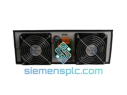
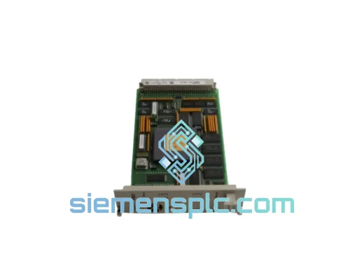
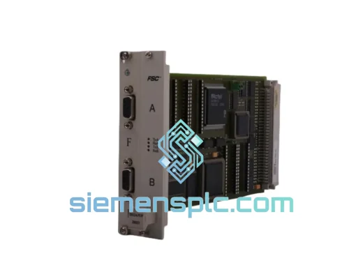
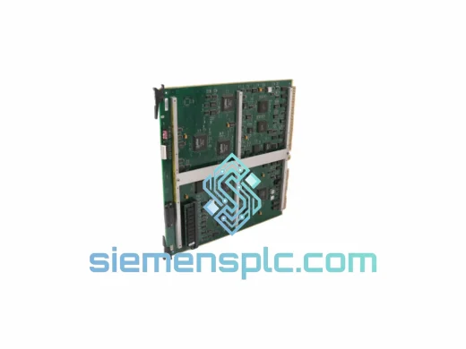
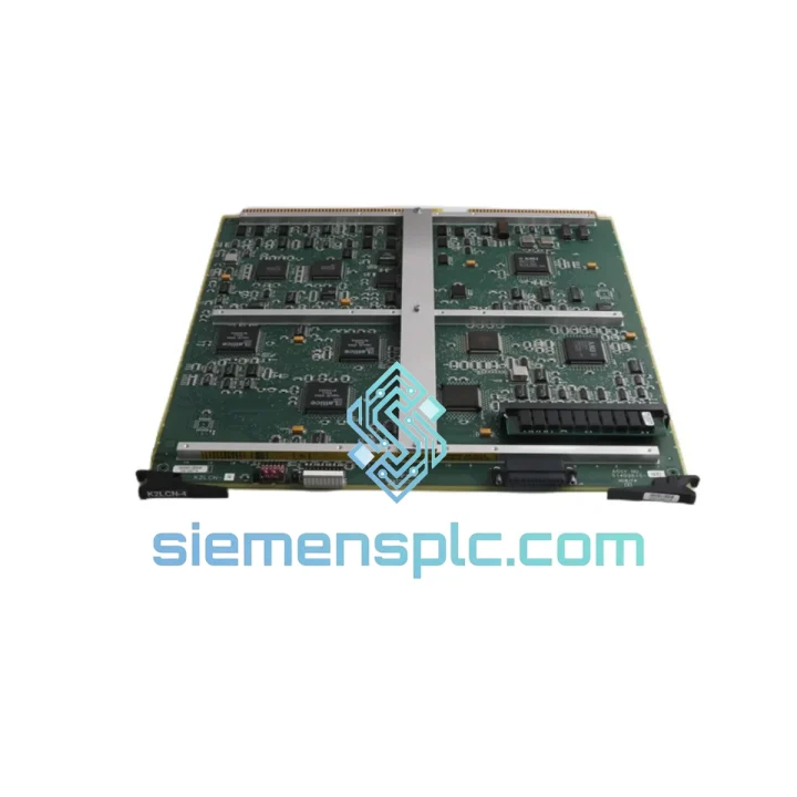
Honeywell K2LCN-4 51402615-400 LCN Interface Board
TDC 3000
Origin US
LCN Interface Board
Request verified availability, condition, replacement risk review, packing options and courier lead time for 51402615-400.
Click Request Quote and the part number is inserted into the inquiry form automatically.
Core fields for model confirmation and RFQ routing. Detailed product narrative remains below.
The Honeywell 51402615-400 is the passive signal distribution substrate at the core of every TDC 3000 and TotalPlant Solution (TPS) control node chassis. It carries no embedded logic, no firmware, and no configurable state. Its electrical performance is determined entirely by physical construction: PCB layer stack-up, differential pair impedance geometry, connector metallurgy, and ground plane continuity. Every LCN arbitration handshake, every I/O scan cycle, and every diagnostic status frame exchanged between daughter cards traverses the copper traces of this board. Its function in the control loop is foundational — no software tuning or controller configuration can compensate for signal integrity degradation at the physical layer.
The -400 hardware revision is the production-stable configuration of this board family. Compared to earlier dash-number variants, the -400 incorporates a refined PCB stack-up that tightens differential pair impedance tolerance on LCN bus trace pairs, reducing reflected signal energy at each slot connector interface. This directly lowers the bit error rate on the LCN bus during sustained high-traffic conditions — coordinated batch sequence execution, plant-wide alarm floods, or simultaneous multi-controller data acquisition bursts. In installations where earlier revisions exhibited marginal LCN bus performance under peak load, substituting a -400 revision board has resolved the issue without any software or configuration change.
Real-time Stock & RFQ: [email protected] | WhatsApp: +86 18359268345
| Parameter | Specification |
|---|---|
| Part Number | 51402615-400 |
| Manufacturer | Honeywell Process Solutions |
| Module Classification | Passive LCN Backplane Interconnect Board |
| Compatible Platforms | Honeywell TDC 3000, TotalPlant Solution (TPS) |
| Hardware Revision | -400 (production-stable) |
| Bus Topology | Honeywell LCN proprietary parallel bus, passive signal routing |
| Logic Supply Voltage | 5 VDC ± 5% |
| Analog Power Rails | ±15 VDC distributed to analog I/O daughter cards per slot |
| Differential Pair Impedance Tolerance | ±10% across all LCN bus trace pairs |
| Propagation Delay Skew | < 200 ps across parallel bus lines |
| PCB Substrate | Multi-layer FR4, glass transition temperature Tg > 130 °C |
| Edge Connector Plating | Hard gold, minimum 30 µin thickness |
| Rated Connector Insertion Cycles | ≥ 500 per slot position |
| Operating Temperature | 0 °C to +60 °C |
| Storage Temperature | -40 °C to +85 °C |
| Relative Humidity (Operating) | 5% to 95% RH, non-condensing |
| Chassis Compatibility | Drop-in fit across all TDC 3000 / TPS card cage generations; no mechanical modification required |
| Approximate Board Weight | 720 g |
| Warranty | 12 months from confirmed dispatch date, covering functional defects under normal operating conditions |
The 51402615-400 contains no active components — no microcontroller, no FPGA, no ASIC, no firmware image. Every electrical characteristic is fixed at the point of manufacture and remains constant across the service life of the unit. This architecture eliminates two entire failure categories: firmware corruption and configuration error. The board requires no commissioning procedure after installation; it reaches full operational readiness upon chassis power application.
Ground Plane Architecture and EMC Attenuation: The inner ground plane layer spans the full board area without interruption beneath all signal routing layers. This geometry establishes a low-inductance return path for all high-frequency currents on the LCN bus traces. Common-mode noise coupled from external sources — variable-frequency motor drives, transformer inrush transients, high-current bus switching events — is attenuated before it can reach the signal layer. Chassis ground bonding is implemented at two spatially separated points along the board’s longitudinal axis. This dual-bond topology prevents ground potential gradients from developing across the board length, a failure mode that produces correlated bus error events at the switching frequency of nearby power electronics and is frequently misdiagnosed as a daughter card fault.
Slot-Level Fault Containment via Series Termination: Each daughter card slot incorporates series termination resistors on all signal lines at the connector interface. If a daughter card develops a low-impedance fault — from component failure, moisture ingress, or physical damage — the termination resistors limit the fault current injected into the shared bus. The bus remains at a defined logic level, and all remaining daughter cards continue executing their scan cycles without interruption. This containment is a structural property of the board, not a software feature, and operates without controller intervention or configuration.
Connector Metallurgy and Long-Term Contact Integrity: Hard gold plating at a minimum of 30 µin on both the backplane slot contacts and the daughter card edge fingers maintains contact resistance below 10 mΩ across the rated 500-cycle insertion life. In a typical TDC 3000 installation, most slots accumulate fewer than 20 card insertions over a decade of operation. The actual connector wear in service is therefore a small fraction of the rated envelope — directly relevant when evaluating refurbished units: a board with documented low insertion history retains connector performance characteristics close to those of a new unit.
Impedance-Controlled Trace Routing: The -400 revision applies controlled-impedance routing to all LCN bus differential pairs. Trace width and dielectric spacing are held to tolerances that maintain characteristic impedance within ±10% across the full board length. At the LCN bus clock rates used in TDC 3000 and TPS systems, uncontrolled impedance discontinuities produce reflections that degrade setup-and-hold timing margins at each slot connector. The -400 revision’s tighter impedance control directly preserves those margins, keeping the LCN bus within its specified bit error rate envelope under maximum slot population and peak traffic load.
Power Rail Decoupling Architecture: Bulk decoupling capacitors are distributed at regular intervals along the 5 VDC and ±15 VDC power rails on the backplane. This distributed decoupling strategy limits the impedance of the power distribution network at frequencies corresponding to the LCN bus clock harmonics and daughter card switching transients. Without adequate decoupling, power rail impedance at these frequencies produces supply voltage perturbations that corrupt logic threshold margins on the bus — a failure mode that manifests as intermittent parity errors under high I/O scan load and is difficult to reproduce in bench testing outside the chassis environment.
Every Honeywell 51402615-400 unit offered through siemensplc.com undergoes a structured pre-dispatch verification process before release to available inventory. Physical inspection covers PCB surface condition across all layers visible at board edges, solder joint integrity at all through-hole and surface-mount locations, connector pin geometry and plating condition at all slot interfaces, and component seating integrity for all passive components. Boards showing evidence of prior rework, connector damage, or PCB delamination are rejected at this stage regardless of electrical test results.
Electrical verification is performed using a dedicated test fixture that replicates the TDC 3000 chassis power distribution and bus termination environment. All backplane bus signal lines are tested for continuity and isolation. Power distribution rails are verified for correct voltage delivery at each slot position. Contact resistance is measured at representative connector positions using a four-wire Kelvin measurement method. Units that do not satisfy all acceptance criteria are quarantined and removed from available stock without exception.
Sourcing is limited to decommissioned plant upgrade projects with documented equipment provenance, authorized distributor surplus inventory, and OEM factory stock where accessible. Each unit carries a traceability record documenting source, inspection date, and test results — provided to customers upon request, supporting compliance requirements in regulated industries where component traceability is a formal audit requirement under IEC and FDA frameworks.
Electrostatic discharge protection follows IEC 61340-5-1. Boards are sealed in anti-static bags with humidity indicator cards, nested in conductive foam-lined rigid inner cartons, and outer-packed in double-wall corrugated export cartons rated for international air freight handling loads. Export documentation — commercial invoice, packing list, and certificate of conformance — is prepared for all international shipments.
In-stock units are dispatched from Xiamen, China within 1–3 business days of order confirmation. International express freight via DHL, FedEx, or UPS delivers to most destinations in Europe, the Middle East, Southeast Asia, and the Americas within 3–7 business days from dispatch. Orders confirmed before 14:00 CST can be prioritized for same-day dispatch — contact us directly to arrange expedited handling.
Email: [email protected]
WhatsApp: +86 18359268345
Web: siemensplc.com
Location: Xiamen, China
© 2026 siemensplc.com. All rights reserved.
We check the full part number, brand, series and visible nameplate information before quotation.
Sales confirms stock path, condition option, quantity and realistic lead time for export dispatch.
DHL, FedEx, UPS or buyer courier arrangements can be reviewed with packing requirements.
Similar brand or category products for fast comparison and multi-item RFQ lists.