Honeywell
RFQ Ready
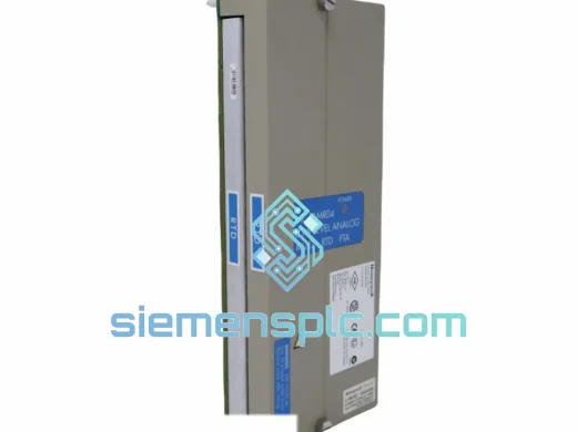
Honeywell DC-TAIX01 Analog Input Module
TDC 3000
Origin US
DCS Analog Input Module
Request verified availability, condition, replacement risk review, packing options and courier lead time for 8C-PDILA1.
Click Request Quote and the part number is inserted into the inquiry form automatically.
Core fields for model confirmation and RFQ routing. Detailed product narrative remains below.
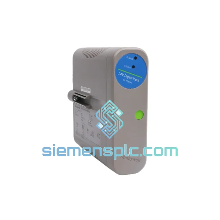
The 8C-PDILA1 (catalog reference 51454471-175) occupies a defined functional position within the Honeywell TDC 3000 and Total Plant Solution (TPS) I/O subsystem: it serves as the discrete field-signal acquisition front-end for the Process Manager (PM) and Advanced Process Manager (APM) card files. Each of its eight channels independently converts a 24V DC field-level binary state — generated by limit switches, proximity sensors, solenoid valve feedback contacts, or motor control center auxiliary contacts — into a latched digital word that the PM/APM controller reads over the internal card-file backplane during every scan cycle. The module does not perform analog-to-digital conversion, pulse counting, or frequency measurement; its architecture is optimized for deterministic, low-latency acquisition of on/off field states in continuous-process plant environments.
Within the TDC 3000 signal chain, the 8C-PDILA1 sits between the field termination assembly (FTA) and the PM/APM controller. Field wiring lands on the FTA (typically 51304485-100 or 51304485-150), which routes signals through the I/O ribbon cable to the card-edge connector of the 8C-PDILA1. The module’s optical isolators decouple field-side ground references from the backplane logic ground, a design decision that eliminates common-mode noise injection from field cable shields and motor-drive return currents. The isolated input register is polled by the PM/APM at the configured scan rate — typically 100 ms to 500 ms depending on controller loading — and the resulting 8-bit input word is mapped to process database points accessible across the Universal Control Network (UCN).
Real-time Stock & RFQ: [email protected] | WhatsApp: +86 18359268345
| Parameter | Value |
|---|---|
| Part Number | 8C-PDILA1 |
| Catalog Suffix | 51454471-175 |
| Input Channels | 8, individually isolated |
| Nominal Input Voltage | 24V DC |
| Input Voltage Range | 18–30V DC |
| Logic ON Threshold | ≥ 11V DC |
| Logic OFF Threshold | ≤ 5V DC |
| Input Current per Channel | ≈ 7 mA @ 24V DC |
| Isolation Type | Optical (channel-to-backplane) |
| Backplane Power Draw | ≤ 1.5W (5V DC rail) |
| Scan Rate | 100–500 ms (PM/APM controller-dependent) |
| Card-Edge Connector | 32-pin DIN, standard TDC 3000 I/O profile |
| Form Factor | Single-width plug-in card |
| Operating Temperature | 0°C to +60°C |
| Storage Temperature | −40°C to +70°C |
| Relative Humidity | 5–95% RH, non-condensing |
| Vibration Compliance | IEC 68-2-6 |
| EMC Certification | CE (EMC Directive) |
| Safety Listing | UL (process control equipment) |
| Weight | ≈ 300 g |
| Warranty | 12 months from dispatch date |
The 8C-PDILA1’s internal architecture reflects the design constraints of continuous-process DCS environments, where field cable runs routinely exceed 300 m and share cable trays with medium-voltage motor feeders and variable-frequency drives (VFDs). Three hardware design decisions are particularly relevant to system integrators:
Optical Isolation Architecture: Each of the eight input channels uses a dedicated optocoupler rather than a shared isolation barrier. This per-channel isolation topology means that a ground fault on one field circuit — for example, a shorted cable shield on a limit switch loop — does not degrade the isolation integrity of the remaining seven channels. The optocoupler forward-current threshold is set to activate reliably at 11V DC, providing a 6V margin above the OFF threshold of 5V DC. This 6V dead band prevents false triggering from capacitively coupled interference on long cable runs, which can induce transient voltages of 2–4V on unloaded conductors in high-noise environments.
Backplane Interface and Scan Determinism: The module presents its 8-bit input register to the PM/APM backplane as a memory-mapped I/O location. The controller reads this register synchronously within each scan cycle, meaning input state changes are captured with a worst-case latency equal to one full scan period. For a 100 ms scan rate, the maximum detection delay for a field event is 100 ms — a deterministic bound that is essential for alarm management systems where event timestamps must be correlated across multiple I/O cards. The module does not buffer historical state changes; only the current input state is available to the controller.
EMC Design and Conducted Immunity: The 8C-PDILA1’s input circuit includes RC filtering ahead of the optocoupler input stage. This passive filter attenuates high-frequency conducted interference — typically generated by VFD switching transients at 2–16 kHz — before it reaches the optocoupler threshold comparator. The filter time constant is selected to pass the slowest expected field signal (a mechanically actuated limit switch with a 20 ms bounce period) while rejecting interference at frequencies above approximately 500 Hz. This design eliminates the need for external signal conditioners or surge suppressors in standard DCS cabinet installations.
Every 8C-PDILA1 unit dispatched from our Xiamen, China facility is a genuine Honeywell-manufactured component. Units are sourced through verified industrial surplus channels, decommissioned plant upgrade programs, and authorized distributors. Before dispatch, each card passes a structured 4-stage inspection protocol:
International shipments depart from Xiamen via DHL Express, FedEx International Priority, or UPS Worldwide Expedited. Transit times to major industrial hubs: Europe 3–5 business days, North America 4–6 business days, Middle East 3–4 business days, Southeast Asia 2–3 business days. Export documentation — commercial invoice, packing list, and certificate of origin — is prepared to comply with destination country customs requirements. Emergency plant-maintenance shipments can be processed same-day for orders confirmed before 14:00 CST.
Email: [email protected]
WhatsApp: +86 18359268345
Web: siemensplc.com
Location: Xiamen, China
© 2026
We check the full part number, brand, series and visible nameplate information before quotation.
Sales confirms stock path, condition option, quantity and realistic lead time for export dispatch.
DHL, FedEx, UPS or buyer courier arrangements can be reviewed with packing requirements.
Similar brand or category products for fast comparison and multi-item RFQ lists.