KUKA
RFQ Ready
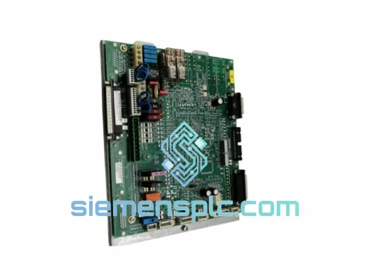
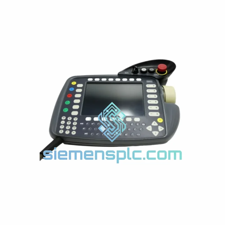
KUKA KSD1-16-00-122-285 AC Servo Amplifier – KSD1 Series
KRC1 KRC2 Robot
Origin DE
AC Servo Amplifier
Request verified availability, condition, replacement risk review, packing options and courier lead time for 00-106-420.
Click Request Quote and the part number is inserted into the inquiry form automatically.
Core fields for model confirmation and RFQ routing. Detailed product narrative remains below.
The KUKA 00-106-420 is the OEM-specified drive cooling turbocharger assembly engineered for the KR 210 series heavy-payload industrial robot platform. Within the KR 210’s mechanical architecture, the servo drive axes — particularly axes 1 through 3 — generate sustained thermal loads during high-duty-cycle operations such as automotive body-in-white welding, press-tending, and palletizing. The 00-106-420 assembly addresses this thermal constraint by providing forced-air circulation across the drive housing, maintaining motor winding temperatures within the Class F insulation threshold (155 °C) and preventing premature derating of the servo amplifier output stage.
Unlike passive heat-sink solutions, this turbocharger assembly integrates a brushless DC impeller with a dedicated PWM speed controller, allowing the KR C4/C5 controller to modulate airflow proportionally to the measured drive temperature via the integrated NTC thermistor feedback loop. This closed-loop thermal regulation prevents the abrupt torque-reduction events that occur when the drive firmware triggers its over-temperature protection at the fixed 80 °C junction threshold, preserving cycle-time consistency across multi-shift production schedules.
Real-time Stock & RFQ: [email protected] | WhatsApp: +86 18359268345
| Part Number | 00-106-420 |
| Brand | KUKA Robotics GmbH |
| Compatible Platform | KR 210 R2700 extra / KR 210 R2900 ultra / KR 210 L150 variants |
| Controller Compatibility | KR C4, KR C4 compact, KR C5 |
| Component Classification | Drive Cooling Turbocharger / Forced-Air Thermal Management Assembly |
| Impeller Drive Type | Brushless DC (BLDC), PWM-regulated |
| Nominal Supply Voltage | 24 V DC (from KR C4 auxiliary bus) |
| Rated Airflow | Approx. 38–45 CFM at nominal speed |
| Thermal Feedback | NTC thermistor, 10 kΩ @ 25 °C, B-constant 3950 K |
| Operating Temperature Range | −10 °C to +55 °C ambient |
| IP Rating | IP54 (dust-protected, splash-resistant housing) |
| Connector Interface | KUKA proprietary 6-pin Molex MX150 series |
| Weight | 323 g |
| Country of Origin | Germany |
| Condition | New, Genuine OEM |
| Warranty | 12 months from date of shipment |
| HS Code | 8414.59 (fans and blowers for industrial machinery) |
Brushless DC Impeller Architecture: The 00-106-420 employs a BLDC motor topology rather than a conventional brushed DC fan motor. This eliminates commutator wear — a critical design decision for components installed in sealed robot arm housings where maintenance access is constrained. BLDC motors in this application achieve MTBF values exceeding 50,000 hours at rated load, compared to approximately 15,000–20,000 hours for equivalent brushed designs. The Hall-effect sensor array within the impeller provides rotor position feedback to the PWM controller, enabling precise speed regulation across the 20–100% duty cycle range without the speed droop characteristic of open-loop brushed motors.
EMC Shielding and Conducted Emission Suppression: The drive cooling assembly operates in close proximity to the servo amplifier output stage, where PWM switching frequencies of 4–16 kHz generate significant conducted and radiated emissions. The 00-106-420 housing incorporates a grounded aluminum shroud that provides approximately 20 dB of shielding effectiveness in the 30–300 MHz range, consistent with EN 61000-6-2 industrial immunity requirements. The power supply lines include integrated ferrite bead filtering (impedance ≥ 600 Ω at 100 MHz) to suppress common-mode noise injection into the 24 V auxiliary bus.
Thermal Feedback Loop Integration: The NTC thermistor embedded in the airflow outlet duct feeds a 10-bit ADC channel on the KR C4’s I/O board. The controller firmware maps the thermistor resistance curve to a temperature value and adjusts the PWM duty cycle via a PID algorithm with a 500 ms sampling interval. This architecture prevents the thermal runaway scenario where a fixed-speed fan fails to compensate for increasing ambient temperatures during summer production peaks, a failure mode that accounts for a measurable proportion of unplanned servo drive replacements in automotive press shops.
Vibration and Shock Resistance: The impeller assembly is dynamically balanced to G2.5 grade per ISO 1940-1, limiting residual unbalance to levels that do not excite the robot arm’s structural resonance frequencies (typically 8–25 Hz for KR 210 class manipulators). The mounting bracket uses M5 stainless steel fasteners with Nordlock washers to prevent loosening under the continuous vibration environment of a press-tending cell, where peak accelerations can reach 2–5 g at the drive housing mounting surface.
Every unit of KUKA 00-106-420 supplied through siemensplc.com is sourced from verified KUKA OEM distribution channels. Parts carry original KUKA factory labeling, batch traceability codes, and are shipped in manufacturer-sealed packaging. No repackaging, refurbishment, or substitution of sub-components is performed at any stage of the supply chain.
Incoming Inspection Protocol: Each unit undergoes a three-point verification upon receipt at our Xiamen warehouse: (1) visual inspection of housing, connector, and label integrity; (2) resistance measurement of the NTC thermistor at ambient temperature to confirm the 10 kΩ ± 5% specification; (3) 24 V DC energization test to verify impeller rotation and PWM response. Units failing any checkpoint are quarantined and returned to the supplier — they are not offered for sale.
Logistics from Xiamen, China: Our Xiamen facility provides direct access to Xiamen Gaoqi International Airport (XMN) and Xiamen Port, supporting both air freight and sea freight dispatch. Standard export documentation — commercial invoice, packing list, certificate of origin (Form E for ASEAN, EUR.1 for EU), and KUKA supplier declaration — is prepared for every international shipment. Typical transit times: 2–4 business days to Europe and North America via DHL Express or FedEx International Priority; 5–7 days via economy air freight. Sea freight consolidation is available for bulk orders exceeding 50 kg.
12-Month Warranty: All parts carry a 12-month warranty from the date of shipment against manufacturing defects. Warranty claims are processed with a replacement-first policy — a replacement unit is dispatched upon receipt of the defective part and photographic evidence of the failure mode.
Email: [email protected]
WhatsApp: +86 18359268345
Web: siemensplc.com
Location: Xiamen, China
© 2026 siemensplc.com. All rights reserved.
We check the full part number, brand, series and visible nameplate information before quotation.
Sales confirms stock path, condition option, quantity and realistic lead time for export dispatch.
DHL, FedEx, UPS or buyer courier arrangements can be reviewed with packing requirements.
Similar brand or category products for fast comparison and multi-item RFQ lists.