KUKA
RFQ Ready
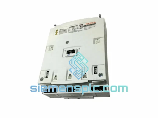
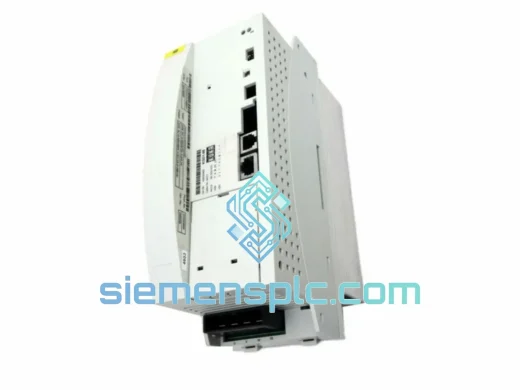
KUKA KSD1-16-00-122-285 AC Servo Amplifier – KSD1 Series
KRC1 KRC2 Robot
Origin DE
AC Servo Amplifier
Request verified availability, condition, replacement risk review, packing options and courier lead time for C2-KSD1-16-00-105-350.
Click Request Quote and the part number is inserted into the inquiry form automatically.
Core fields for model confirmation and RFQ routing. Detailed product narrative remains below.
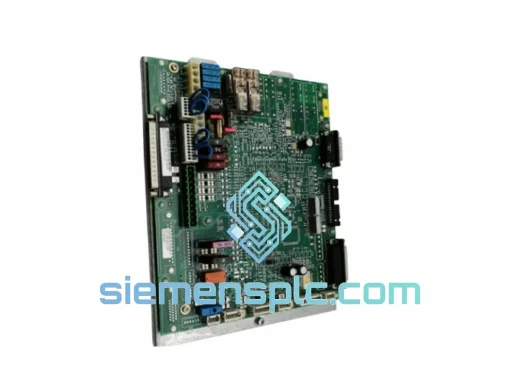
The KUKA C2-KSD1-16-00-105-350 is a single-axis servo drive module purpose-built for the KR C2 robot controller cabinet. It occupies the final power conversion stage between the Drive System Electronics (DSE) board and the AC servo motor, translating a 540 VDC bus potential into a regulated three-phase output whose amplitude and frequency are modulated at 8 kHz via an IGBT H-bridge. The 16 A continuous current rating defines its torque delivery envelope, covering the axis current demands of KR 6, KR 16, and selected axes of KR 30 robot variants operating under standard duty cycles in automotive, foundry, and general-purpose assembly environments.
Unlike general-purpose servo amplifiers that operate as self-contained closed-loop controllers, the C2-KSD1-16-00-105-350 functions as a torque-mode actuator node within a distributed motion architecture. Velocity and torque setpoints originate at the DSE board, which executes the position control loop at a 1 ms servo cycle. The drive receives these commands over the KR C2 internal drive bus — an INTERBUS-S derivative operating at deterministic cycle intervals — and executes PWM switching accordingly. Position feedback from the motor resolver is routed separately to the RDC (Resolver-to-Digital Converter) card, digitized at 16-bit angular resolution, and returned to the DSE for loop closure. This separation of the power switching domain from the precision measurement domain is a deliberate architectural decision that prevents IGBT switching transients from corrupting encoder data integrity.
In multi-axis KR C2 cabinets, up to six C2-KSD1 drives share a common DC bus supplied by the KPS-600 or KPS-1500 power supply module. Regenerative braking energy from decelerating axes is fed back onto the shared DC bus and absorbed by other axes under acceleration, reducing net energy draw from the mains supply and lowering thermal load on the cabinet’s cooling system. The C2-KSD1-16-00-105-350 participates in this energy exchange passively — no configuration is required — as the shared bus topology is inherent to the KR C2 cabinet design.
Real-time Stock & RFQ: [email protected] | WhatsApp: +86 18359268345
| Parameter | Specification |
|---|---|
| Part Number | C2-KSD1-16-00-105-350 |
| Manufacturer | KUKA Roboter GmbH |
| Controller Series | KR C2 |
| Module Function | Single-Axis Servo Drive (Torque Mode) |
| Continuous Output Current | 16 A RMS |
| Peak Output Current | ~32 A (≤2 s, 200% rated) |
| DC Bus Input Voltage | 540 VDC nominal (KPS-600 / KPS-1500) |
| Output Phase Configuration | 3-phase AC, variable frequency |
| PWM Switching Frequency | 8 kHz (IGBT stage) |
| Communication Interface | KR C2 internal drive bus (DSE-IBS / DSE-RDW) |
| Position Feedback Path | Resolver → RDC card → DSE (16-bit resolution) |
| Thermal Protection | NTC thermistor, controlled deceleration ramp on overtemperature |
| Overcurrent Protection | Hardware-latched, fault code reported via internal bus |
| Mounting Interface | Guided rail insertion, KR C2 cabinet slot |
| Approximate Weight | 560 g |
| Country of Origin | Germany |
| Warranty | 12 months from shipment date |
IGBT Gate Drive Isolation Architecture: The three-phase output stage uses IGBTs arranged in a full H-bridge topology. Gate drive signals cross an optocoupler isolation barrier rated for reinforced insulation, ensuring that high-side switching transients — with dV/dt rates that can exceed 5 kV/µs at 540 VDC bus — remain confined to the power domain. This galvanic separation prevents common-mode noise injection into the low-voltage logic and communication circuits that share the cabinet backplane, a critical requirement in multi-axis cabinets where six drives switch simultaneously.
EMC Conducted Emission Suppression: A multi-stage LC filter on the DC bus input attenuates switching harmonics before they propagate back toward the KPS power supply and the mains transformer. Differential-mode chokes combined with X/Y capacitor networks address the 150 kHz–30 MHz conducted emission band, maintaining compliance with EN 61800-3 Category C2 limits applicable to industrial drive systems. PCB layer stackup routes high-current traces on inner copper layers with continuous ground planes on outer layers, minimizing the effective radiating loop area of the switching circuit.
Distributed Position Loop Architecture: The C2-KSD1-16-00-105-350 does not close the position loop internally. Motor resolver signals travel via shielded cable to the KR C2’s RDC card, which performs resolver-to-digital conversion at 16-bit angular resolution. The DSE board reads this data at each 1 ms servo cycle, computes the torque command, and transmits it to the drive over the internal bus. The drive executes the torque command at the 8 kHz PWM level. This two-tier architecture — 1 ms position loop at DSE, 125 µs PWM execution at drive — provides the bandwidth necessary for the KR C2’s ±0.1 mm path accuracy specification under dynamic load conditions.
Thermal Reporting and Controlled Shutdown Logic: An NTC thermistor embedded in the IGBT module reports junction temperature to the DSE at each communication cycle. When temperature approaches the programmed threshold (nominally 85°C junction), the DSE initiates a velocity ramp-down before asserting a fault state. This controlled deceleration prevents abrupt torque removal from the robot arm, which would otherwise generate mechanical shock loads on the gearbox and wrist assembly. The approach contrasts with simpler drives that assert an immediate hardware shutdown on overtemperature, requiring manual fault reset and production restart.
Fault Register and Diagnostic Bus Reporting: Hardware fault conditions — overcurrent, DC bus undervoltage, overtemperature, communication timeout — are latched in a dedicated fault register within the drive’s local logic. The DSE polls this register at each bus cycle and maps the fault codes to KUKA’s KRC diagnostic numbering scheme. Fault codes appear on the KCP2 teach pendant display and are logged in the KRC error history, enabling maintenance engineers to identify the specific fault condition without requiring oscilloscope-level diagnostics at the drive terminals.
Each C2-KSD1-16-00-105-350 unit shipped from our Xiamen, China facility is sourced through verified supply channels with documented traceability to KUKA Roboter GmbH’s authorized distribution network. Pre-shipment inspection covers physical integrity assessment (connector pin condition, housing, label authenticity, serial number format verification), ESD-safe packaging in anti-static bags with foam cushioning rated for air freight vibration profiles per ISTA 2A, and documentation completeness review.
International shipments depart Xiamen via DHL Express, FedEx International Priority, or UPS Worldwide Express. Typical transit times are 3–5 business days to Europe, 2–4 business days to Southeast Asia, and 4–7 business days to North America. Each shipment includes a commercial invoice, packing list, and HS code documentation (HS 8537.10) to support customs clearance. Country-of-origin documentation (Germany) is provided on request to support preferential tariff applications under applicable trade agreements.
All units carry a 12-month warranty against manufacturing defects and premature failure under normal operating conditions. Warranty claims receive a target response within 2 business days. In confirmed failure cases, replacement units are dispatched before return of the defective module to minimize production downtime for B2B customers operating under production SLAs.
Email: [email protected]
WhatsApp: +86 18359268345
Web: siemensplc.com
Location: Xiamen, China
© 2026 siemensplc.com. All rights reserved.
We check the full part number, brand, series and visible nameplate information before quotation.
Sales confirms stock path, condition option, quantity and realistic lead time for export dispatch.
DHL, FedEx, UPS or buyer courier arrangements can be reviewed with packing requirements.
Similar brand or category products for fast comparison and multi-item RFQ lists.