Mitsubishi Electric
RFQ Ready
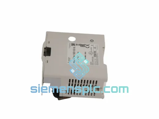
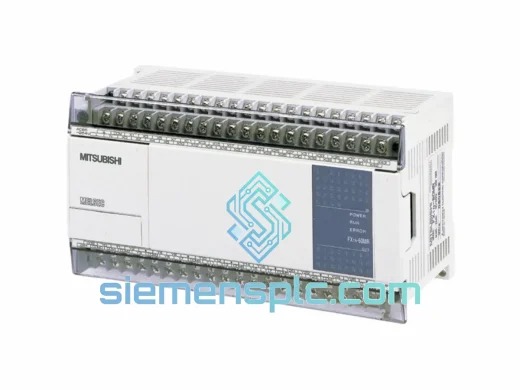
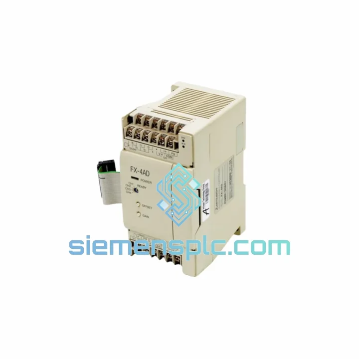
Mitsubishi FX3U-4AD-PT-ADP Analog Input Adapter
MELSEC FX
Origin JP
PLC Analog Input Adapter
Request verified availability, condition, replacement risk review, packing options and courier lead time for FX-4AD.
Click Request Quote and the part number is inserted into the inquiry form automatically.
Core fields for model confirmation and RFQ routing. Detailed product narrative remains below.
The FX-4AD occupies a well-defined role in the MELSEC FX control architecture: it serves as the analog acquisition boundary between field instrumentation and the FX CPU’s digital processing domain. Where a base unit’s onboard I/O handles discrete switching, the FX-4AD extends the system’s observability into the continuous-signal world — pressure transmitters, thermocouple conditioners, flow meters, and position transducers all terminate here before their values enter the PLC scan cycle as structured buffer memory (BFM) data.
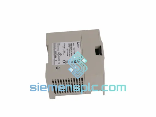
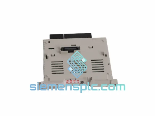
The module mounts directly to the right side of any FX1N, FX2N, FX2NC, FX3U, FX3UC, or FX3G base unit via the proprietary extension bus connector. No external power supply is required; the module draws DC 5 V at 55 mA from the bus itself. Up to eight special function modules can be chained on a single base unit, subject to the cumulative bus current budget. Each FX-4AD occupies one module position and is addressed by its physical slot index (0–7), which the CPU references in FROM and TO ladder instructions.
Signal acquisition follows a sequential, channel-by-channel architecture. The on-board successive-approximation ADC samples each enabled channel at a fixed 6 ms interval, yielding a worst-case total conversion latency of 15 ms across all four channels when all are active. Disabling unused channels via BFM #0 (channel enable register) reduces this latency proportionally — a two-channel configuration completes in approximately 6 ms, which is relevant for fast-loop applications such as web tension control or servo feedback monitoring.
Each channel accepts either a voltage signal (DC 0–10 V or ±10 V bipolar) or a current signal (DC 4–20 mA or 0–20 mA), selectable by wiring configuration rather than firmware jumpers. Voltage inputs present a 200 kΩ input impedance, ensuring negligible loading on high-impedance sensor outputs. Current inputs terminate into a precision 250 Ω shunt resistor, converting the loop current to a proportional voltage before the ADC stage. The 12-bit resolution maps the full input span to a 4,096-count digital word, giving a voltage LSB of approximately 2.44 mV on the 0–10 V range and a current LSB of approximately 3.9 µA on the 4–20 mA range.
Photocoupler isolation is implemented between the field-side terminal block and the FX extension bus. This galvanic barrier suppresses common-mode noise and ground-loop currents that are endemic in industrial panel environments where multiple field devices share a common earth reference. The isolation boundary also protects the CPU backplane from field-side transient events — motor drive switching noise, solenoid flyback, and welding equipment interference — that would otherwise corrupt BFM data or damage the CPU’s internal bus logic.
Accuracy is specified at ±1% of full scale at 25 °C ambient. Over the full operating temperature range of 0 °C to +55 °C, gain drift and offset drift remain within the bounds of the ±1% envelope for most industrial process applications. For applications requiring tighter absolute accuracy, the FX-4AD supports a two-point offset/gain calibration procedure via BFM #1 (offset value) and BFM #2 (gain value), allowing field calibration against a known reference standard without modifying the ladder program.
The module’s BFM map is straightforward: BFM #0 controls channel enable/disable; BFM #1–#4 hold the current converted values for channels 1–4 respectively; BFM #5 stores the averaging count (1–4096 samples) for each channel independently. Averaging is implemented in hardware, not in the CPU scan, which means the CPU always reads a pre-averaged value without consuming scan-cycle time for filtering. A 16-sample average, for instance, reduces high-frequency noise by approximately 12 dB without any ladder logic overhead.
Real-time Stock & RFQ: [email protected] | WhatsApp: +86 18359268345
| Parameter | Specification |
|---|---|
| Model Number | FX-4AD |
| Manufacturer | Mitsubishi Electric |
| Platform / Series | MELSEC FX Series |
| Analog Input Channels | 4 (independently configurable) |
| Voltage Input Range | DC 0 to +10 V; DC −10 V to +10 V (bipolar) |
| Current Input Range | DC 4–20 mA; DC 0–20 mA |
| ADC Resolution | 12-bit (digital output: 0–4095 counts) |
| Conversion Speed | 6 ms per channel (15 ms for 4 channels active) |
| Input Impedance — Voltage | 200 kΩ |
| Input Impedance — Current | 250 Ω (precision shunt) |
| Accuracy | ±1% of full scale at 25 °C |
| Hardware Averaging | 1–4096 samples per channel (BFM #5) |
| Isolation Method | Photocoupler (field side ↔ extension bus) |
| Bus Power Consumption | 55 mA at DC 5 V (from FX extension bus) |
| External Power Required | None |
| Compatible Base Units | FX1N, FX2N, FX2NC, FX3U, FX3UC, FX3G |
| Max Modules per Base Unit | 8 special function modules |
| CPU Access Method | FROM / TO ladder instructions; BFM addressing |
| Operating Temperature | 0 °C to +55 °C |
| Storage Temperature | −20 °C to +70 °C |
| Relative Humidity | 5% to 95% RH, non-condensing |
| Dimensions (W × H × D) | 55 × 90 × 87 mm |
| Weight | Approx. 260 g |
| Mounting | DIN rail or direct panel mount |
| Certifications | CE, UL, cUL |
| Country of Origin | Japan |
| Warranty | 12 months against manufacturing defects |
Successive-Approximation ADC Architecture: The FX-4AD employs a successive-approximation register (SAR) ADC topology rather than a sigma-delta or flash architecture. SAR converters offer a fixed, predictable conversion time per sample — a property that is architecturally important in a PLC module where the CPU scan cycle must account for BFM read latency. The 6 ms/channel conversion time is deterministic across the full input range and temperature envelope, which allows control engineers to budget scan-cycle timing without statistical uncertainty.
Photocoupler Isolation Barrier: The isolation stage uses high-speed optocouplers rated for the data transfer rates required by the FX extension bus protocol. The isolation boundary is placed between the analog signal conditioning circuitry (field side) and the digital bus interface (CPU side). This topology means that even a complete field-side wiring fault — including a short to mains potential — cannot propagate destructive energy onto the CPU backplane. The common-mode rejection ratio (CMRR) provided by the photocoupler stage suppresses differential noise voltages that appear equally on both signal conductors, which is the dominant noise mechanism in long cable runs through electrically noisy panels.
Hardware Averaging Filter: The on-board averaging engine accumulates between 1 and 4,096 consecutive ADC samples and presents the arithmetic mean to BFM #1–#4. This is implemented in dedicated module firmware, not in the FX CPU scan. The practical consequence is that a 256-sample average — which reduces broadband noise by approximately 24 dB — imposes zero additional ladder scan time. The averaging count is set independently per channel, allowing a fast-responding channel (e.g., a pressure transducer in a closed-loop PID) to use a low count while a slow process variable (e.g., a temperature sensor) uses a high count for maximum noise rejection.
EMC Design Considerations: The module’s PCB layout routes analog signal traces on layers physically separated from the digital bus interface traces, minimizing capacitive coupling between the high-frequency bus signals and the sensitive analog front-end. The terminal block is positioned at the module’s field-side edge, keeping field wiring away from the bus connector. Ferrite bead filtering on the DC 5 V bus supply line attenuates high-frequency switching noise injected by adjacent modules or the base unit’s internal SMPS.
Offset/Gain Calibration via BFM: Factory calibration sets the offset and gain coefficients stored in non-volatile memory. Field recalibration is performed by writing known reference values to BFM #1 (offset) and BFM #2 (gain) using the TO instruction. This two-point calibration corrects for sensor cable resistance, terminal block contact resistance, and long-term component drift without requiring module removal or factory service.
Every FX-4AD unit dispatched from our Xiamen, China facility is a genuine Mitsubishi Electric product sourced through verified supply channels with full traceability documentation. Incoming inspection covers three verification layers: physical label authentication (date code, country-of-origin marking, holographic security features cross-referenced against Mitsubishi Electric reference samples), PCB marking verification against known-good reference units, and a functional power-on test confirming bus communication and ADC output within specification.
Units are packed in anti-static bags with foam cushioning inside original-style export cartons. A packing list, inspection report, and certificate of conformance are included with each shipment. For orders requiring third-party inspection or specific documentation (SGS, BV, or customer-specific incoming QC forms), these can be arranged at the quotation stage.
Logistics from Xiamen port covers all major global destinations. Standard air freight to Europe, North America, Southeast Asia, and the Middle East typically delivers within 5–10 business days. Express courier (DHL, FedEx, UPS) options are available for urgent requirements, with door-to-door transit times of 3–5 business days to most destinations. Sea freight consolidation is available for bulk orders. All shipments include tracking numbers and commercial invoices with accurate HS code classification for customs clearance. The 12-month warranty covers manufacturing defects; replacement units are dispatched within 2 business days of confirmed fault diagnosis.
Email: [email protected]
WhatsApp: +86 18359268345
Web: siemensplc.com
Location: Xiamen, China
© 2026 siemensplc.com. All rights reserved.
We check the full part number, brand, series and visible nameplate information before quotation.
Sales confirms stock path, condition option, quantity and realistic lead time for export dispatch.
DHL, FedEx, UPS or buyer courier arrangements can be reviewed with packing requirements.
Similar brand or category products for fast comparison and multi-item RFQ lists.