Mitsubishi Electric
RFQ Ready
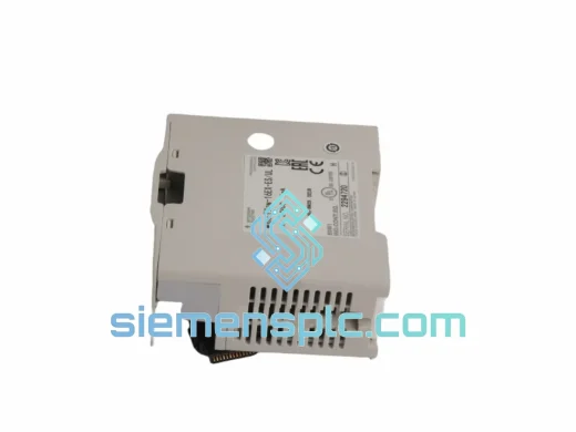
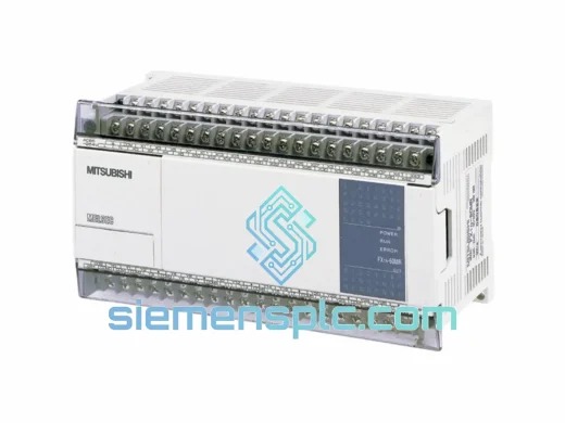
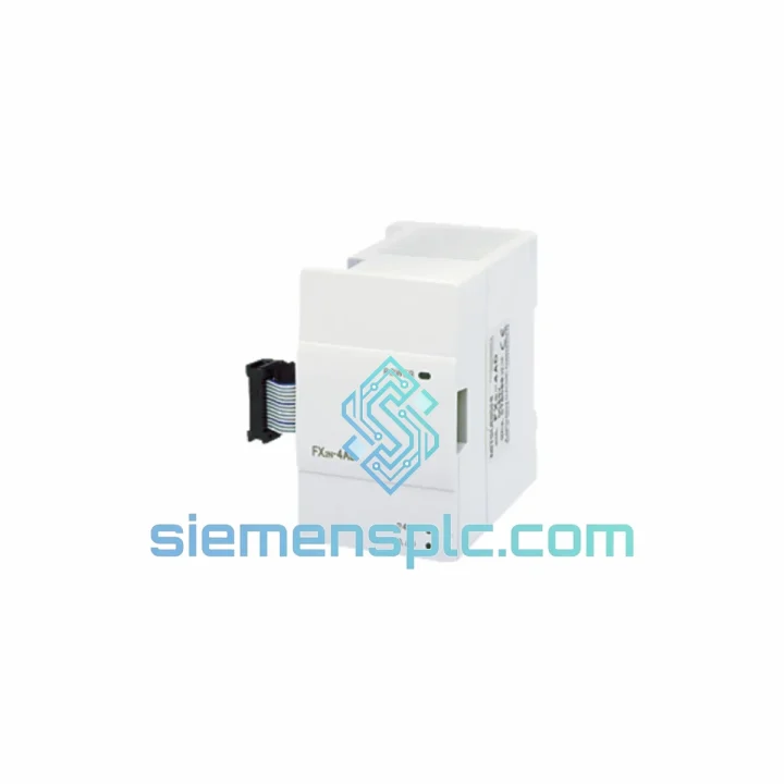
Mitsubishi FX3U-4AD-PT-ADP Analog Input Adapter
MELSEC FX
Origin JP
PLC Analog Input Adapter
Request verified availability, condition, replacement risk review, packing options and courier lead time for FX2N-4AD.
Click Request Quote and the part number is inserted into the inquiry form automatically.
Core fields for model confirmation and RFQ routing. Detailed product narrative remains below.
The FX2N-4AD is a special function module (SFM) engineered for the Mitsubishi MELSEC FX2N programmable controller platform. It provides four independent analog input channels capable of accepting either voltage signals in the range of −10 V to +10 V DC or current loop signals from 4 mA to 20 mA, selectable per channel via jumper configuration. The module performs analog-to-digital conversion at 12-bit resolution for voltage inputs and 11-bit plus sign for current inputs, delivering a digital output range of −2048 to +2047 (voltage) or 0 to 2000 (current). Conversion time is 6 ms per channel, yielding a full four-channel scan cycle of approximately 15 ms — a deterministic acquisition rate that satisfies the timing requirements of closed-loop PID control in process automation environments.
Data exchange between the FX2N-4AD and the host CPU is accomplished through the FX2N extension bus using FROM/TO buffer memory instructions. The module occupies eight I/O points on the FX2N bus and maps its channel data into a 32-word buffer memory space (BFM #0–#31). No dedicated software driver is required; all configuration and data retrieval are handled through standard ladder logic FROM/TO instructions, making integration straightforward for engineers already familiar with the FX2N instruction set.
Real-time Stock & RFQ: [email protected] | WhatsApp: +86 18359268345
| Parameter | Specification |
|---|---|
| Model Number | FX2N-4AD |
| Manufacturer | Mitsubishi Electric |
| Series | MELSEC FX2N |
| Module Classification | Special Function Module – Analog Input |
| Number of Input Channels | 4 (CH1, CH2, CH3, CH4) |
| Input Signal Type | Voltage: −10 V to +10 V DC; Current: 4–20 mA (jumper-selectable per channel) |
| A/D Resolution | Voltage: 12-bit (−2048 to +2047); Current: 11-bit + sign (0 to 2000) |
| Conversion Speed | 6 ms per channel; 15 ms for all 4 channels |
| Input Impedance (Voltage) | 200 kΩ minimum |
| Input Impedance (Current) | 250 Ω |
| Absolute Maximum Input | Voltage: ±15 V DC; Current: 30 mA |
| Isolation Method | Optocoupler isolation between analog inputs and PLC bus |
| Internal Power Consumption | 5 VDC, 30 mA (supplied from FX2N bus) |
| External Power Supply | 24 VDC, 55 mA (required for analog circuit) |
| Bus I/O Points Occupied | 8 points |
| Buffer Memory (BFM) | 32 words (BFM #0–#31) |
| Operating Temperature | 0°C to +55°C |
| Storage Temperature | −25°C to +75°C |
| Relative Humidity | 5% to 95% RH (non-condensing) |
| Vibration Resistance | 10–57 Hz: 0.075 mm amplitude; 57–150 Hz: 9.8 m/s² |
| Shock Resistance | 147 m/s², 3 axes |
| Dimensions (W × H × D) | 55 mm × 90 mm × 87 mm |
| Weight | Approx. 210 g |
| Certifications | CE (EMC Directive 2014/30/EU, LVD 2014/35/EU), UL 508, cUL, RoHS |
| Compatible CPUs | FX2N-16M through FX2N-128M (all variants); FX2NC with CNV-BC adapter |
| Programming Instructions | FROM / TO (ladder logic); compatible with GX Developer, GX Works2 |
| Warranty | 12 months from date of shipment |
The FX2N-4AD implements a successive approximation register (SAR) ADC architecture, which provides a favorable balance between conversion speed and resolution for industrial process signals. Each of the four channels is served by a dedicated sample-and-hold circuit that captures the input signal at the start of the conversion cycle, ensuring that the digitized value represents a stable snapshot rather than a time-averaged approximation. This architecture eliminates inter-channel crosstalk that can occur in multiplexed single-ADC designs where settling time is insufficient between channel switches.
Optocoupler Isolation Architecture: The galvanic isolation barrier between the analog input stage and the FX2N backplane bus is implemented using high-speed optocouplers rated for a minimum isolation voltage of 500 V AC. This barrier serves two distinct engineering purposes. First, it prevents ground loop currents — common in industrial environments where field instruments and PLCs share different ground reference potentials — from corrupting the digitized signal. Second, it protects the CPU module and backplane from transient overvoltage events originating at the field wiring terminals, which can reach several hundred volts during inductive load switching or lightning-induced surges on long cable runs.
EMC Design Considerations: The module’s PCB layout follows a split-plane strategy: the analog ground plane (AGND) and digital ground plane (DGND) are connected at a single star point adjacent to the isolation barrier. This topology minimizes the return current path for high-frequency digital switching noise, preventing it from coupling into the analog signal traces. Input filter capacitors at each channel terminal provide first-order low-pass filtering with a cutoff frequency designed to attenuate conducted interference above the Nyquist frequency of the ADC, reducing aliasing artifacts in noisy plant environments.
Buffer Memory Architecture: The 32-word BFM is implemented as a dual-port RAM accessible from both the analog processing side and the FX2N bus interface logic. BFM #0–#3 hold the converted digital values for CH1–CH4 respectively. BFM #14 and #15 provide channel enable/disable control, allowing unused channels to be deactivated to reduce the effective scan cycle contribution. BFM #29 contains an error status word with individual bit flags for each channel, enabling the CPU program to detect open-circuit current loop conditions (signal below 2 mA) or overvoltage conditions without requiring external diagnostic hardware.
Jumper-Based Channel Mode Selection: Voltage/current mode selection is performed via physical jumpers on the module PCB rather than software registers. This hardware-enforced configuration prevents accidental mode switching through program errors, which is a relevant safety consideration in processes where connecting a voltage source to a current-mode input (250 Ω shunt) would result in excessive current draw and potential terminal damage.
Every FX2N-4AD unit supplied through siemensplc.com is sourced as genuine Mitsubishi Electric OEM hardware. Units are procured through verified industrial distribution channels with full supply chain traceability. Prior to dispatch, each module undergoes a structured inspection protocol: visual examination of label integrity, terminal block condition, and housing for evidence of rework or remarking; functional power-on verification; and cross-reference of serial number format against known genuine production batches.
Shipments originate from our warehouse in Xiamen, China — a major logistics hub with direct access to international freight forwarding services via Xiamen Gaoqi International Airport and Xiamen Port. Standard export packaging consists of anti-static ESD shielding bags, foam-lined cartons, and moisture-barrier outer packaging, ensuring the module arrives in the same condition it left our facility regardless of transit duration or handling conditions.
Typical dispatch lead time for in-stock units is 1–3 business days from order confirmation. International express delivery (DHL, FedEx, UPS) reaches most destinations in Asia-Pacific within 3–5 business days, Europe within 5–7 business days, and North America within 5–8 business days. All shipments include tracking numbers and are covered by transit insurance. Export documentation — including commercial invoice, packing list, and certificate of origin — is prepared in compliance with the import requirements of the destination country. A 12-month warranty covers manufacturing defects and functional failures under normal operating conditions.
Email: [email protected]
WhatsApp: +86 18359268345
Web: siemensplc.com
Location: Xiamen, China
© 2026 siemensplc.com. All rights reserved.
We check the full part number, brand, series and visible nameplate information before quotation.
Sales confirms stock path, condition option, quantity and realistic lead time for export dispatch.
DHL, FedEx, UPS or buyer courier arrangements can be reviewed with packing requirements.
Similar brand or category products for fast comparison and multi-item RFQ lists.