Mitsubishi Electric
RFQ Ready
MITSUBISHI QX524 BN634A636G51 Digital Input Module
MELSEC-Q
Origin JP
Digital Input Module
Request verified availability, condition, replacement risk review, packing options and courier lead time for MELSEC-Q.
Click Request Quote and the part number is inserted into the inquiry form automatically.
Core fields for model confirmation and RFQ routing. Detailed product narrative remains below.
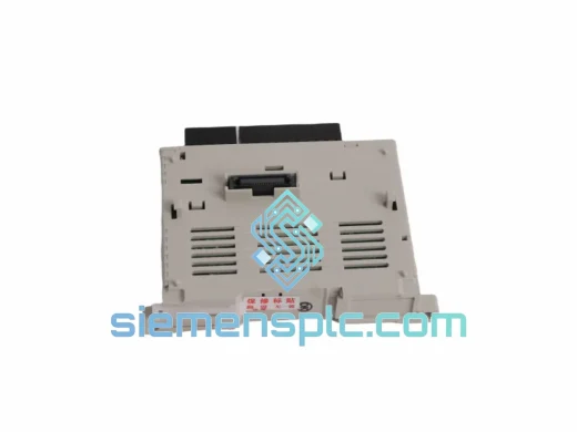
The MY51 is a 16-point relay contact output module designed for integration into Mitsubishi Electric’s MELSEC-Q series programmable controller platform. It occupies a single slot on any Q-series main or extension base unit and presents 16 independent Form-A (normally open) relay contacts to the field wiring layer. The relay coil-and-armature mechanism provides galvanic separation between the 5 VDC backplane logic domain and the field-side load circuit, which may operate at voltages up to 240 VAC or 30 VDC. This physical isolation barrier is the defining characteristic that differentiates relay output modules from transistor output types: there is no semiconductor junction in the current path between the PLC logic and the field device, eliminating leakage current concerns and enabling direct switching of AC loads without external interface relays.
Within a MELSEC-Q control loop, the CPU module writes a 16-bit output word to the shared memory area on the synchronous backplane bus at the conclusion of each scan cycle. The MY51’s bus interface ASIC reads the word assigned to its slot address and drives the 16 relay coil transistor switches accordingly. Relay states are latched and held stable between scan cycles, meaning that coil energization is not subject to bus arbitration timing variations. This deterministic output behavior is essential in applications where relay actuation sequence directly governs mechanical or process events — for example, in conveyor interlock logic or batch reactor valve sequencing — where an unintended output glitch during a CPU mode transition could trigger a process fault or safety shutdown.
The module’s 16 output points are organized into four independent common terminal groups of four points each. Each common can be connected to a separate field supply voltage, allowing a single MY51 to simultaneously switch 24 VDC solenoid valves on COM1, 120 VAC motor starter coils on COM2, and 240 VAC heating element contactors on COM3 and COM4 — all within one slot. This segmented common architecture eliminates the need for separate relay output modules per voltage class, reducing slot consumption on the base unit and simplifying panel wiring documentation.
Real-time Stock & RFQ: [email protected] | WhatsApp: +86 18359268345
| Parameter | Specification |
|---|---|
| Model Number | MY51 |
| Series | MELSEC-Q |
| Manufacturer | Mitsubishi Electric |
| Output Type | Relay Contact (Form-A, Normally Open) |
| Number of Output Points | 16 Points |
| Output Common Configuration | 4 commons × 4 points per common |
| Rated Load Voltage (AC) | 240 VAC, 50/60 Hz |
| Rated Load Voltage (DC) | 30 VDC |
| Maximum Load Current per Point | 2 A (resistive load) |
| Maximum Load Current per Common | 8 A |
| Minimum Switchable Load | 1 mA at 5 VDC |
| Isolation Method | Mechanical relay (galvanic isolation, coil-to-contact) |
| Coil-to-Contact Isolation Voltage | 1,500 VAC (dielectric withstand) |
| Response Time OFF→ON | ≤ 10 ms |
| Response Time ON→OFF | ≤ 12 ms |
| Internal Current Consumption (5 VDC backplane) | 90 mA (typical) |
| Mechanical Relay Life | ≥ 20,000,000 operations (no load) |
| Electrical Relay Life | ≥ 300,000 operations (rated resistive load) |
| Operating Temperature | 0 °C to +55 °C |
| Storage Temperature | −25 °C to +75 °C |
| Relative Humidity | 5% to 95% RH, non-condensing |
| Vibration Resistance | 5–9 Hz: 3.5 mm amplitude; 9–150 Hz: 9.8 m/s² |
| Shock Resistance | 147 m/s², 3 axes, 3 shocks each |
| Module Weight | Approx. 1,020 g |
| Compatible Base Units | Q3□B, Q5□B, Q6□B, QA1S6□B (main and extension) |
| Applicable Standards | CE (LVD + EMC Directive), UL 508, cUL, RoHS, IEC 61131-2 |
| Warranty | 12 months from date of shipment |
The MY51’s internal circuit architecture addresses three distinct engineering constraints that govern relay output module design in industrial PLC applications: coil drive integrity, contact protection, and EMC boundary management.
Coil Drive Transistor and Flyback Suppression: Each of the 16 relay coils is driven by a dedicated NPN transistor switch whose base is controlled by the output latch register. The latch register is updated by the backplane bus interface ASIC at each scan cycle. A flyback diode is placed in anti-parallel across each relay coil to clamp the inductive voltage transient generated at coil de-energization. Without this clamp, the collapsing magnetic field in the coil would produce a voltage spike — typically 5 to 10 times the supply voltage — that could drive the transistor into avalanche breakdown and degrade its switching characteristics over time. The integrated flyback diode eliminates this failure mode at the module level, though RC snubbers or metal oxide varistors (MOVs) across inductive field loads remain recommended to limit contact arc energy and extend electrical relay life.
Segmented Common Terminal Architecture: The four-common structure is implemented at the terminal block level with physically separated common bus bars. Each common bus bar is electrically isolated from adjacent commons on the terminal block connector body, preventing accidental bridging between voltage domains during field wiring installation. The terminal block is rated for the full 8 A per common current, with conductor cross-section recommendations specified in the hardware manual to maintain voltage drop within acceptable limits at maximum load.
EMC Boundary at the Module Interface: The MY51 meets IEC 61131-2 immunity requirements, including 1 kV conducted disturbance on I/O lines and 2 kV EFT burst per IEC 61000-4-4. The relay contact gap — with a minimum open-circuit clearance consistent with 1,500 VAC dielectric withstand — provides inherent high-voltage isolation that no optocoupler-based transistor output module can match without additional external isolation components. The module PCB routes high-current contact traces on the field-side layer, separated from the low-level logic traces on the backplane-side layer, minimizing capacitive coupling between the two domains. The module housing connects to the base unit chassis ground rail through the mounting connector, providing a defined low-impedance path for common-mode noise currents induced on the field wiring.
Backplane Bus Latch Behavior During CPU Mode Transitions: When the MELSEC-Q CPU transitions from RUN to STOP mode, the output module behavior is governed by the parameter setting in GX Works: outputs can be set to hold their last state or reset to OFF. The MY51’s bus interface ASIC holds the relay coil states at the last latched value until a new bus write cycle updates the output register. This means that during a CPU STOP event, relay states do not glitch or momentarily de-energize and re-energize — a behavior that would be mechanically destructive in applications driving contactors or solenoid valves with high inrush currents.
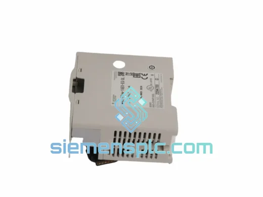
Each MY51 unit shipped from our Xiamen, China facility is sourced through verified Mitsubishi Electric authorized distribution channels. Every module carries the original Mitsubishi Electric factory label, production date code, and a serial number traceable to the manufacturing batch record. Prior to dispatch, units pass a structured incoming inspection protocol: visual examination for physical damage and counterfeit label indicators, relay coil continuity measurement on all 16 channels, contact resistance verification using a four-wire milliohm measurement method, and cross-reference of the module’s part number and revision marking against the Mitsubishi Electric official product database.
Packaging follows ESD-safe handling procedures throughout: modules are sealed in anti-static poly bags with humidity indicator cards, cushioned in EPE foam inserts contoured to the module profile, and packed in double-wall corrugated cartons rated for international air and sea freight drop and compression loads. For time-critical procurement requirements, DHL Express and FedEx International Priority services from Xiamen Gaoqi International Airport deliver to major industrial centers in Europe, North America, the Middle East, and Southeast Asia within 3 to 5 business days under normal customs clearance conditions. Sea freight consolidation is available for volume orders. All shipments are accompanied by a commercial invoice, packing list, and certificate of conformance. HS code 8537.10 applies in most import jurisdictions; buyers should confirm local tariff classification with their customs broker prior to order placement.
A 12-month warranty against manufacturing defects is provided from the confirmed shipment date. Warranty claims are initiated by email with photographic documentation of the defect; replacement units are dispatched upon defect verification. For regulated industries requiring full material traceability, a material certificate and factory test report are available upon request at the time of order confirmation.
Email: [email protected]
WhatsApp: +86 18359268345
Web: siemensplc.com
Location: Xiamen, China
© 2026 siemensplc.com. All rights reserved.
We check the full part number, brand, series and visible nameplate information before quotation.
Sales confirms stock path, condition option, quantity and realistic lead time for export dispatch.
DHL, FedEx, UPS or buyer courier arrangements can be reviewed with packing requirements.
Similar brand or category products for fast comparison and multi-item RFQ lists.