Schneider Electric
RFQ Ready
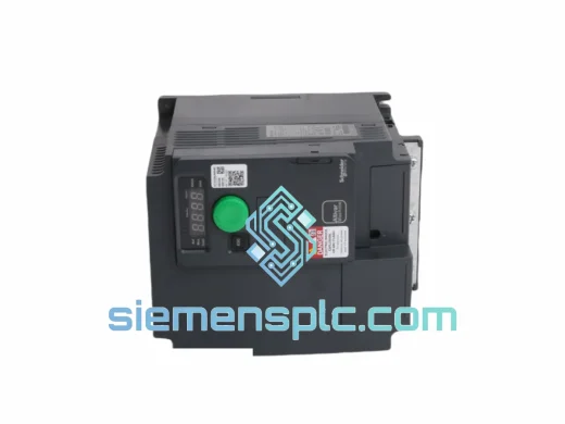
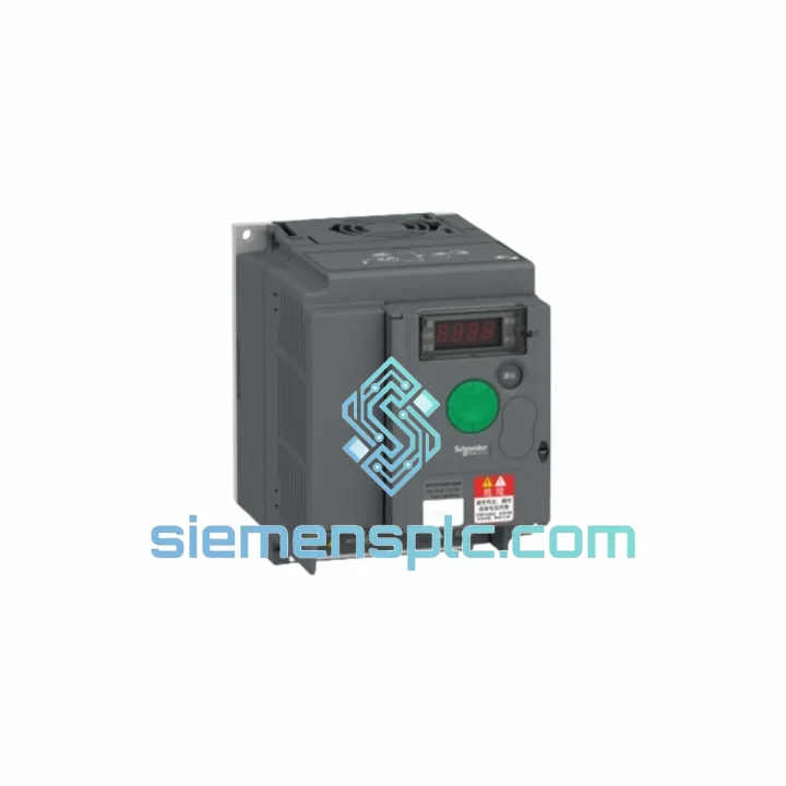
Schneider Electric ATV320U55N4B Variable Frequency Drive
Altivar
Origin FR
Variable Frequency Drive
Request verified availability, condition, replacement risk review, packing options and courier lead time for ATV310HU75N4.
Click Request Quote and the part number is inserted into the inquiry form automatically.
Core fields for model confirmation and RFQ routing. Detailed product narrative remains below.
The ATV310HU75N4 occupies a well-defined position in the Altivar 310 product matrix: a three-phase, 380–460 V input, 7.5 kW (10 HP) variable frequency drive engineered for continuous-duty motor speed regulation in pump, fan, conveyor, and general-purpose machine applications. Unlike general-purpose inverters that require extensive parameter mapping at commissioning, the ATV310 platform ships with application-specific macros pre-loaded in non-volatile EEPROM, reducing first-run setup to parameter verification rather than full configuration. The drive’s control architecture separates the power stage from the signal-processing board via optocoupler isolation on all digital input lines, a design choice that directly limits common-mode noise propagation from the IGBT switching stage into the control logic domain.
At 7.5 kW, the ATV310HU75N4 sits at the upper boundary of the compact ATV310 frame range, where thermal management transitions from passive convection to forced-air cooling via an integrated fan mounted on the heatsink extrusion. The rated output current of 17 A at 400 V provides a 10–15% headroom margin over the nameplate current of most standard IEC 7.5 kW four-pole induction motors, accommodating brief overload transients without triggering OC (overcurrent) fault trips during acceleration ramps.
Real-time Stock & RFQ: [email protected] | WhatsApp: +86 18359268345
| Part Number / SKU | ATV310HU75N4 |
| Brand | Schneider Electric |
| Series | Altivar 310 (ATV310) |
| Motor Power Rating | 7.5 kW / 10 HP |
| Input Voltage | Three-phase 380–460 V AC (±10%) |
| Input Frequency | 50 / 60 Hz |
| Output Voltage | Three-phase 0–460 V AC (PWM) |
| Output Frequency Range | 0.5–500 Hz |
| Rated Output Current | 17 A (at 400 V) |
| Transient Overload Capacity | 150% of rated current for 60 s |
| PWM Switching Frequency | 2–16 kHz (adjustable, default 4 kHz) |
| Control Modes | V/f (Volts-per-Hertz), Sensorless Flux Vector (SVC) |
| Speed Regulation Accuracy (SVC) | ±10% of nominal slip |
| Braking | Built-in braking transistor; external resistor on PA/PB terminals |
| Digital Inputs | 6 × programmable, 24 V DC logic, optocoupler-isolated |
| Analog Inputs | AI1: 0–10 V / 0–20 mA; AI2: 0–10 V / 0–20 mA |
| Relay Outputs | 2 × Form C relay (R1: fault; R2: programmable), 250 V AC / 2 A |
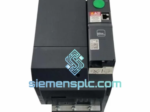
| Communication | Modbus RTU via RJ45 (native, no gateway required) |
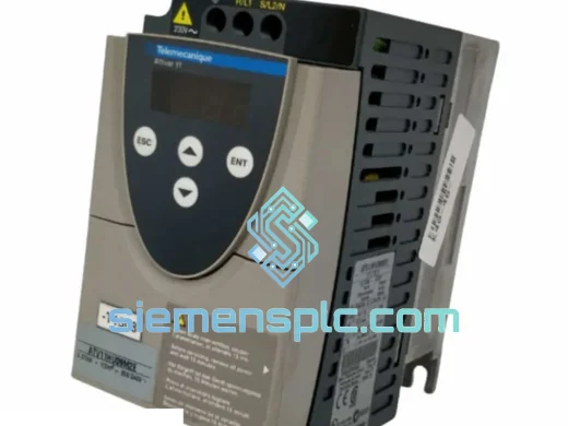
| HMI / Display | Integrated 4-digit LED display with 4-key navigation |
| Internal EMC Filter | Integrated, EN 61800-3 Category C2 compliant |
| Protection Rating | IP20 standard; IP21 with optional top cover kit |
| Operating Temperature | −10 °C to +50 °C (derate above 40 °C) |
| Storage Temperature | −25 °C to +70 °C |
| Relative Humidity | 5–95% non-condensing |
| Altitude | ≤ 1000 m without derating; derate 1% per 100 m above |
| Dimensions (H × W × D) | 270 × 130 × 195 mm |
| Weight | 2.68 kg |
| Certifications | CE, UL, cUL, RoHS 2 |
| Country of Origin | China (CN) |
| Warranty | 12 months from date of dispatch |
The ATV310HU75N4 power stage is built around a three-phase uncontrolled diode rectifier bridge feeding a bulk DC bus capacitor bank. The DC bus voltage at 400 V input nominally sits at approximately 565 V DC under no-load conditions. The IGBT inverter stage uses six discrete IGBT modules with integrated freewheeling diodes, driven by isolated gate driver ICs that enforce a dead-time interval of approximately 2–4 µs between complementary switch pairs to prevent shoot-through. This dead-time is fixed in firmware and is not user-adjustable, which is a deliberate design constraint to protect the power semiconductors under all load conditions.
The internal EMC filter consists of a common-mode choke on the AC input lines and X/Y capacitors to chassis ground. This filter attenuates high-frequency conducted emissions generated by the IGBT switching transitions, achieving EN 61800-3 Category C2 compliance without requiring an external line reactor in most standard industrial installations. For cable runs exceeding 50 m to the motor, Schneider Electric recommends adding an output dV/dt filter to limit the rate of voltage rise at the motor terminals and protect winding insulation from reflected wave stress.
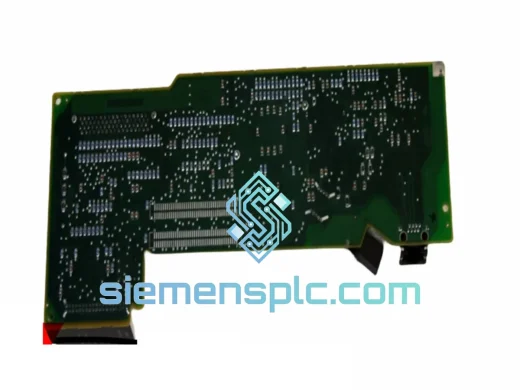
The control board communicates with the power stage gate drivers via a fiber-optic or high-speed digital isolation barrier (implementation varies by production revision), providing galvanic isolation between the 3.3 V logic domain and the 600 V+ power domain. All six digital inputs (DI1–DI6) pass through optocoupler stages rated for 2.5 kV isolation, which suppresses common-mode transients induced by motor cable capacitive coupling or nearby switching equipment. The two analog inputs use differential amplifier front-ends with RC low-pass filtering (cutoff approximately 100 Hz) to reject high-frequency noise on the reference signal lines.
The built-in braking transistor is rated for the full 7.5 kW power class and connects to external braking resistors via the PA/PB terminals. The transistor activates when the DC bus voltage exceeds a threshold of approximately 800 V DC (for 400 V input class), dissipating regenerative energy from decelerating loads. The duty cycle of the braking transistor is firmware-limited to protect the IGBT from thermal overload; for high-inertia loads requiring sustained braking, the external resistor thermal rating must be sized accordingly.
Every ATV310HU75N4 unit dispatched from our Xiamen, China facility is a genuine Schneider Electric product sourced through verified industrial supply channels. Prior to dispatch, each unit undergoes a structured inspection protocol: visual examination of housing integrity, label authenticity verification against Schneider Electric’s holographic security features, and a functional power-on check confirming display operation and parameter access. Units with any evidence of prior installation, modified labels, or non-factory seals are rejected and not offered for sale.
Packaging follows Schneider Electric’s original carton specification where available, or equivalent ESD-protective foam-lined cartons for surplus stock. Each shipment includes a commercial invoice, packing list, and certificate of origin (China). DDP, DAP, and EXW Incoterms are available depending on destination and order volume. Air freight to major industrial hubs in Europe, Southeast Asia, the Middle East, and the Americas typically achieves 3–7 business day transit. Sea freight consolidation is available for volume orders. All export documentation is prepared in compliance with Chinese customs regulations and destination country import requirements.
A 12-month operational warranty covers manufacturing defects and component failures under normal operating conditions as defined by the ATV310 installation manual. Warranty claims are processed through our Xiamen technical team, with advance replacement available for verified critical-path applications subject to prior arrangement.
Email: [email protected]
WhatsApp: +86 18359268345
Web: siemensplc.com
Location: Xiamen, China
© 2026 siemensplc.com. All rights reserved.
We check the full part number, brand, series and visible nameplate information before quotation.
Sales confirms stock path, condition option, quantity and realistic lead time for export dispatch.
DHL, FedEx, UPS or buyer courier arrangements can be reviewed with packing requirements.
Similar brand or category products for fast comparison and multi-item RFQ lists.