Schneider Electric
RFQ Ready
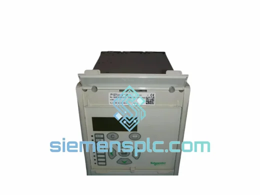
Schneider Electric P127CA1W1D3FC0 Numerical Protection Relay – Sepam Series
Sepam
Origin FR
Numerical Protection Relay
Request verified availability, condition, replacement risk review, packing options and courier lead time for iC65N-3P-C32A.
Click Request Quote and the part number is inserted into the inquiry form automatically.
Core fields for model confirmation and RFQ routing. Detailed product narrative remains below.
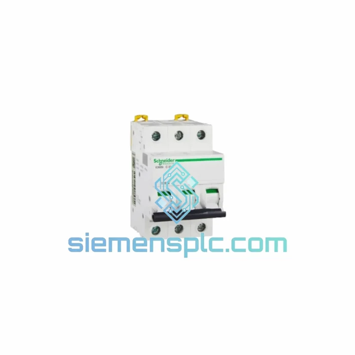
The Schneider Electric iC65N-3P-C32A is a three-pole, 32 A, C-trip-curve miniature circuit breaker belonging to the Acti9 modular device family. In a layered power distribution hierarchy — incomer, sub-distribution, branch circuit — this device operates at the branch-circuit tier, providing coordinated overcurrent and short-circuit protection for loads drawing up to 32 A per phase. Its rated breaking capacity of 10 kA at 230/400 V AC (per IEC/EN 60898-1) positions it correctly for sub-distribution boards located downstream of a 400 V LV transformer with a prospective short-circuit current (PSCC) not exceeding 10 kA at the point of installation.
The C-curve instantaneous release window — 5 to 10 times rated current (160 A to 320 A) — is calibrated for loads with moderate inrush characteristics: general-purpose resistive and inductive feeders, lighting distribution circuits, and direct-on-line (DOL) motor starters where locked-rotor current does not exceed 10 × In. For applications with higher inrush (e.g., large transformer primaries or capacitor banks), the D-curve variant would be the appropriate selection; the iC65N-3P-C32A is not intended for those duty cycles.
Real-time Stock & RFQ: [email protected] | WhatsApp: +86 18359268345
| Parameter | Specification |
|---|---|
| Manufacturer | Schneider Electric |
| Series / Platform | Acti9 iC65N |
| Catalog Reference | iC65N-3P-C32A |
| Number of Poles | 3P — simultaneous trip and reset across all poles |
| Rated Current (In) | 32 A |
| Trip Curve | C — instantaneous release at 5–10 × In (160–320 A) |
| Thermal Overload Range | 1.13 × In (non-trip, cold) to 1.45 × In (trip within 1 h, hot) |
| Rated Operational Voltage (Ue) | 230 V AC (1P+N) / 400 V AC (3P) |
| Rated Insulation Voltage (Ui) | 500 V AC |
| Rated Impulse Withstand Voltage (Uimp) | 6 kV |
| Frequency | 50 Hz / 60 Hz |
| Rated Breaking Capacity (Icn) | 10 kA @ 230/400 V AC — IEC/EN 60898-1 |
| Service Breaking Capacity (Ics) | 7.5 kA (75% of Icn) |
| Utilization Category | A (non-selective, instantaneous) |
| Mounting | 35 mm symmetrical DIN rail per EN 60715 |
| Module Width (per pole) | 18 mm — total 3P assembly: 54 mm |
| Overall Dimensions (H × W × D) | 85 mm × 54 mm × 73 mm |
| Terminal Conductor Cross-Section | 1–25 mm² (solid or stranded Cu/Al, with or without ferrule) |
| Terminal Tightening Torque | 3.5 N·m |
| Degree of Protection | IP20 (IP40 with terminal shields installed) |
| Ambient Operating Temperature | −25 °C to +60 °C (rated at +40 °C; derate above +40 °C) |
| Storage Temperature | −40 °C to +70 °C |
| Relative Humidity (non-condensing) | ≤ 95% RH at +40 °C |
| Mechanical Endurance | 20,000 operating cycles |
| Electrical Endurance | 10,000 cycles at rated current In |
| Gross Weight (3P assembly) | 1,320 g |
| Applicable Standards | IEC/EN 60898-1, IEC/EN 60947-2, CE (LVD 2014/35/EU), RoHS 2011/65/EU, REACH |
| Warranty | 12 months from verified dispatch date |
Dual-Release Mechanism and Trip Latch Geometry
The iC65N-3P-C32A houses two physically independent release elements within a single 54 mm molded-case assembly. The thermal element — a bimetallic strip composed of two bonded metals with differing coefficients of thermal expansion — deflects proportionally to I²R heating. At 1.13 × In (36.2 A), the strip remains within the non-trip zone under cold conditions. At 1.45 × In (46.4 A) sustained for up to 60 minutes from a thermally stabilized state, deflection reaches the trip latch engagement threshold. This inverse-time characteristic is not arbitrary: it mirrors the thermal time constant of copper conductors, ensuring the breaker trips before conductor insulation reaches its rated maximum temperature (typically 70 °C for PVC-insulated cables).
Magnetic Release and Arc Interruption Physics
The magnetic release is a fixed-gap solenoid. When fault current exceeds 5 × In (160 A), the electromagnetic force on the solenoid armature overcomes the calibrated spring preload and drives the armature into the trip bar within 10–20 ms — well within the first half-cycle of a 50 Hz waveform. This sub-cycle response limits the let-through energy (I²t) delivered to downstream conductors and connected equipment. The arc generated at contact separation is directed into a deionizing arc chute: a stack of ferromagnetic steel splitter plates that subdivide the arc into multiple shorter arcs in series, each with its own anode-cathode voltage drop. The cumulative arc voltage exceeds the system voltage, driving fault current to zero before the next natural current zero crossing. This architecture achieves the 10 kA Icn rating without requiring a current-limiting fuse in series.
Trip-Free Mechanism
The toggle mechanism employs a trip-free design per IEC/EN 60898-1 clause 8.6. Even if an external force holds the handle in the ON position — as may occur when a PLC output relay or remote control device energizes a shunt-close coil — the internal trip latch will still release the contacts on a fault condition. This prevents the hazardous scenario of a faulted circuit being held closed by automation logic, a critical safety requirement in machine control panels operating under IEC 62061 or ISO 13849 functional safety frameworks.
EMC and Creepage Design
The DIN rail mounting clip provides a direct, low-impedance metallic bond between the breaker chassis and the panel earth bar, establishing a reference ground plane that attenuates common-mode conducted interference. The housing material — glass-fiber reinforced thermoplastic — achieves a comparative tracking index (CTI) ≥ 250, classifying it as Material Group II per IEC 60112. This CTI rating ensures adequate creepage distance performance in environments with condensation, dust, or mild chemical contamination, reducing the probability of surface-tracking arcs between adjacent live parts.
Acti9 Modular Accessory Interface
A standardized accessory slot on the top face of the housing accepts the full Acti9 auxiliary device range without breaker removal or panel rewiring. Compatible accessories include: OF auxiliary contact (volt-free status signal, 6 A / 250 V AC), SD fault-trip signal contact, SDE fault-trip signal with differentiation between overload and short-circuit, MX shunt trip coil (24 V DC, 48 V DC, 110 V AC, 230 V AC), MN undervoltage release (208–415 V AC), and the Vigi iC65 residual current add-on module (30 mA, 100 mA, 300 mA, Type A or AC). This field-upgradeable architecture allows protection functionality to be expanded post-commissioning without replacing the base breaker — a significant advantage in facilities where protection requirements evolve with process changes.
All iC65N-3P-C32A units dispatched from siemensplc.com are sourced through traceable Schneider Electric supply channels. Pre-dispatch inspection at our Xiamen facility covers four verification layers:
Xiamen operates as a designated free-trade port with direct air freight connections to Singapore, Dubai, Frankfurt, Los Angeles, and Sydney. Standard DHL/FedEx express transit from Xiamen to most industrial destinations is 3–5 business days. Sea freight consolidation is available for bulk orders. All shipments are accompanied by a commercial invoice, packing list, and certificate of origin. The applicable HS code for this product is 8536.20 (automatic circuit breakers for a voltage not exceeding 1,000 V). Import duty rates vary by destination country; buyers are advised to confirm applicable rates with their customs broker prior to order placement.
Email: [email protected]
WhatsApp: +86 18359268345
Web: siemensplc.com
Location: Xiamen, China
© 2026 siemensplc.com. All rights reserved.
We check the full part number, brand, series and visible nameplate information before quotation.
Sales confirms stock path, condition option, quantity and realistic lead time for export dispatch.
DHL, FedEx, UPS or buyer courier arrangements can be reviewed with packing requirements.
Similar brand or category products for fast comparison and multi-item RFQ lists.