Schneider Electric
RFQ Ready
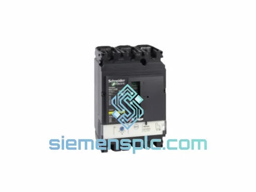
Schneider Electric iC65N-3P-C32A Miniature Circuit Breaker – Acti9
2A C-Curve MCB Acti9 Series
Origin FR
Miniature Circuit Breaker
Request verified availability, condition, replacement risk review, packing options and courier lead time for P127CA1W1D3FC0.
Click Request Quote and the part number is inserted into the inquiry form automatically.
Core fields for model confirmation and RFQ routing. Detailed product narrative remains below.
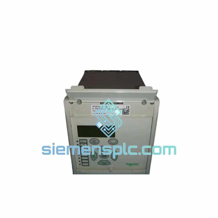
The P127CA1W1D3FC0 is a multi-function numerical protection relay belonging to Schneider Electric’s Sepam platform — a product line engineered specifically for medium-voltage (MV) switchgear, motor control centers, transformer bays, and feeder protection panels operating in the 1 kV to 52 kV range. Unlike legacy electromechanical relays that execute a single protection function per device, the P127CA1W1D3FC0 consolidates overcurrent, earth fault, thermal overload, and directional protection logic into a single 4U panel-mount chassis, reducing wiring complexity, panel footprint, and commissioning time simultaneously.
At its core, the module employs a 32-bit DSP processor executing IEC 60255-compliant protection algorithms at a 1 kHz analog sampling rate. Each protection element is evaluated every 5 ms, yielding a worst-case trip decision latency of under 30 ms from fault inception to contact output — a figure that satisfies the coordination margins required by IEC 60909 short-circuit studies in radial and ring-main MV networks. The relay’s analog front-end accepts standard 1 A or 5 A CT secondaries and 100 V VT secondaries, with a 16-bit ADC providing a dynamic measurement range that covers both load current and fault current without saturation up to 40× rated input.
The P127CA1W1D3FC0 variant designation encodes specific hardware options: the C suffix indicates the communication module fitted (Modbus RTU / IEC 60870-5-103 dual-port), the A1 block specifies the auxiliary power supply range (24–250 V DC / 100–240 V AC universal input), W1 denotes the standard I/O complement (4 configurable output relays + 4 digital inputs), D3 identifies the display and HMI variant (backlit LCD with 4-line alphanumeric readout), and FC0 references the factory-loaded protection function set — in this case, the full feeder and motor protection library including ANSI functions 50, 51, 50N, 51N, 49, 46, 67, and 67N.
Real-time Stock & RFQ: [email protected] | WhatsApp: +86 18359268345
| Parameter | Specification |
|---|---|
| Part Number | P127CA1W1D3FC0 |
| Brand | Schneider Electric |
| Series | Sepam (Numerical Protection Platform) |
| Module Type | Numerical Multi-Function Protection Relay |
| Protection Functions (ANSI) | 50, 51, 50N, 51N, 49, 46, 67, 67N |
| CT Input (Phase) | 1 A or 5 A secondary (selectable) |
| CT Input (Earth) | 1 A or 5 A / 0.2 A (CSH core balance CT) |
| VT Input | 100 V (Ph-Ph) / 57.7 V (Ph-N) |
| ADC Resolution | 16-bit, 1 kHz sampling rate |
| Protection Cycle Time | 5 ms (200 Hz evaluation loop) |
| Trip Output Latency | <30 ms (fault inception to contact closure) |
| Measurement Accuracy | Class 0.5 per IEC 61869 |
| Auxiliary Supply | 24–250 V DC / 100–240 V AC (universal) |
| Power Consumption | ≤15 W (DC) / ≤20 VA (AC) |
| Output Relays | 4 × configurable (NO/NC), 8 A / 250 V AC rated |
| Digital Inputs | 4 × optocoupled, 24–250 V DC compatible |
| Communication Port 1 | RS-485, Modbus RTU (up to 19,200 baud) |
| Communication Port 2 | RS-485, IEC 60870-5-103 |
| HMI Display | 4-line backlit LCD, alphanumeric |
| Event Log | 50 time-stamped events (1 ms resolution) |
| Disturbance Recording | 8 records × 10 s waveform capture |
| Operating Temperature | −25 °C to +70 °C |
| Storage Temperature | −40 °C to +85 °C |
| Relative Humidity | 5–95% non-condensing |
| Front Panel Protection | IP52 |
| Rear Terminal Protection | IP20 |
| Mounting | Panel flush-mount (cutout per IEC 60297) |
| Dimensions (H×W×D) | 4U × 19-inch rack compatible |
| Weight | ~4.46 kg (packaged) |
| Standards | IEC 60255, IEC 61850 (GOOSE-ready), IEC 60870-5-103, CE |
| Country of Origin | France |
| Warranty | 12 months against manufacturing defects |
The P127CA1W1D3FC0 is built around a dual-processor architecture: a dedicated analog front-end processor handles CT/VT signal conditioning and ADC conversion, while the main 32-bit DSP executes protection algorithms and manages I/O arbitration. This separation ensures that a communication bus fault or HMI lockup cannot interrupt the protection execution loop — a design principle mandated by IEC 60255-1 for Class P protection devices.
Optical Isolation on Digital Inputs: All four digital inputs pass through opto-isolators rated at 2.5 kV isolation voltage, preventing ground-loop currents from MV switchgear auxiliary circuits from corrupting the relay’s logic state. The input threshold is hardware-set at 17 V DC minimum, rejecting induced noise on long cable runs without software filtering delays.
EMC Design: The chassis employs a multi-layer PCB with dedicated ground planes and ferrite bead filtering on all I/O lines. The relay meets IEC 61000-4-4 (EFT/Burst, 4 kV) and IEC 61000-4-5 (Surge, 2 kV line-to-earth) immunity levels — the same thresholds required for equipment installed adjacent to MV circuit breakers and disconnectors where switching transients routinely exceed 1 kV peak.
Output Relay Contact Architecture: The four output relays use bifurcated gold-flashed silver contacts, maintaining reliable continuity at currents as low as 10 mA (for PLC digital input circuits) while sustaining 8 A make capacity for direct trip coil energization. Each relay is individually configurable as NO or NC via software, with a hardware watchdog that forces all outputs to a defined fail-safe state within 100 ms of processor fault detection.
Thermal Overload Model (ANSI 49): The thermal image algorithm implements a two-time-constant model per IEC 60255-8, tracking both the stator winding thermal state and the rotor thermal state independently. The model accounts for cooling time constants during motor standstill, preventing nuisance trips on hot restarts while maintaining protection integrity against sustained overloads. The thermal state is stored in non-volatile memory, surviving auxiliary supply interruptions without reset.
Directional Element (ANSI 67/67N): The directional overcurrent element uses a 90° voltage polarization scheme with memory voltage retention for close-in three-phase faults where the polarizing voltage collapses. The memory voltage hold time is 100 ms — sufficient to maintain directional discrimination through the fault clearance cycle of upstream breakers in ring-main configurations.
Every P127CA1W1D3FC0 unit supplied by siemensplc.com is sourced through verified Schneider Electric authorized distribution channels. Each module ships in original Schneider Electric factory packaging with intact tamper-evident seals, a factory-printed serial number label, and the CE Declaration of Conformity document. Serial numbers are cross-referenced against Schneider Electric’s product authentication database prior to dispatch.
Our Xiamen, China operations hub maintains bonded warehouse stock of high-velocity Sepam SKUs, enabling same-day dispatch for in-stock units. International shipments are routed via DHL Express, FedEx International Priority, or UPS Worldwide Expedited depending on destination and urgency. Typical transit times: 3–5 business days to Southeast Asia, 5–7 business days to Europe and the Middle East, 5–8 business days to North America. All shipments include full commercial invoice, packing list, and certificate of origin documentation required for customs clearance in regulated markets.
A 12-month warranty against manufacturing defects is provided on all units. Dead-on-arrival (DOA) units are replaced within 7 business days of confirmed fault report. Pre-shipment functional verification — auxiliary supply power-on, output relay continuity check, and communication port response test — is performed on every unit before dispatch.
Email: [email protected]
WhatsApp: +86 18359268345
Web: siemensplc.com
Location: Xiamen, China
© 2026 siemensplc.com. All rights reserved.
We check the full part number, brand, series and visible nameplate information before quotation.
Sales confirms stock path, condition option, quantity and realistic lead time for export dispatch.
DHL, FedEx, UPS or buyer courier arrangements can be reviewed with packing requirements.
Similar brand or category products for fast comparison and multi-item RFQ lists.