Schneider Electric
RFQ Ready
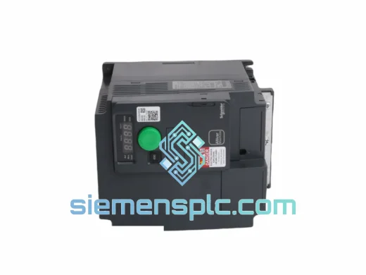
Schneider Electric ATV320U55N4B Variable Frequency Drive
Altivar
Origin FR
Variable Frequency Drive
Request verified availability, condition, replacement risk review, packing options and courier lead time for PN072139P903.
Click Request Quote and the part number is inserted into the inquiry form automatically.
Core fields for model confirmation and RFQ routing. Detailed product narrative remains below.
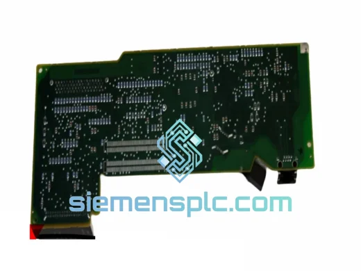
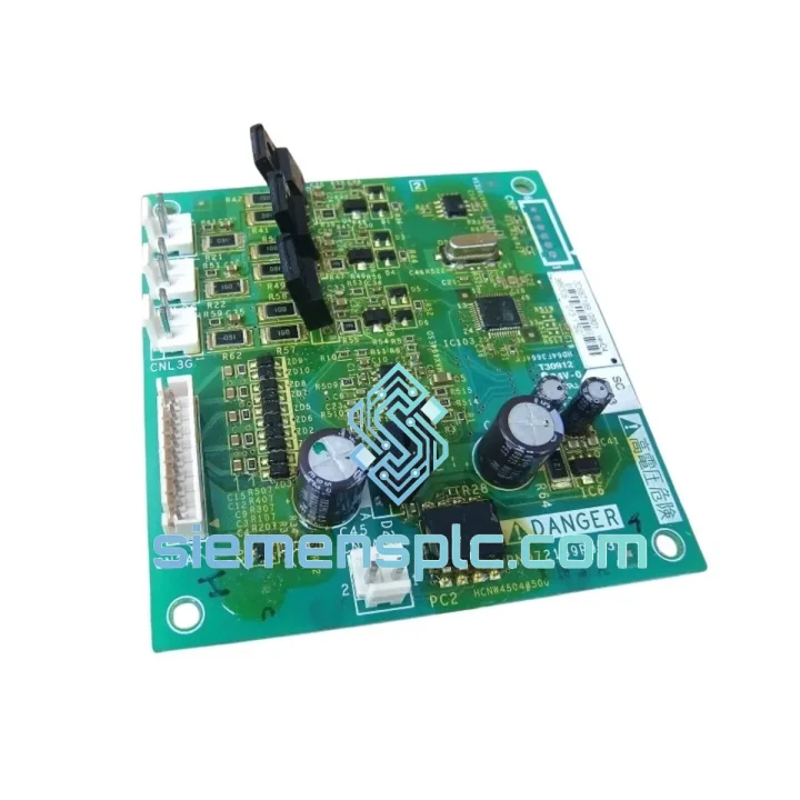
The Schneider Electric PN072139P903 is a dedicated thyristor gate-drive printed circuit board engineered for the ATV61 and ATV71 series variable-frequency drives operating in the 75 kW to 630 kW power frame range. Within the drive’s power conversion topology, this board occupies the interface layer between the digital control section and the silicon-controlled rectifier (SCR) bridge. Its primary function is to generate precisely timed, electrically isolated gate pulses that determine the conduction angle of each thyristor in the three-phase rectifier or regenerative braking assembly.
In a phase-controlled rectifier, the DC bus voltage is a direct function of the firing angle α. A deviation of even a few microseconds in gate pulse timing translates into measurable DC bus ripple, increased harmonic distortion on the AC supply, and thermal stress on the SCR junctions. The PN072139P903 addresses this by deriving its synchronization reference directly from the AC line voltage zero-crossing detection circuit embedded on the board, ensuring firing angle accuracy is maintained independent of upstream control card latency.
The board interfaces with the ATV61/ATV71 main control card via a low-voltage ribbon connector. Gate output signals are routed through pulse transformers that provide galvanic isolation between the logic-level control domain (typically 5 V or 3.3 V CMOS) and the high-voltage gate-cathode circuit of each SCR. This isolation architecture prevents common-mode transients generated during thyristor switching — which can reach dV/dt values exceeding 500 V/µs — from coupling back into the microprocessor-based control section.
Genuine PN072139P903 boards are factory-calibrated to Schneider Electric’s OEM gate pulse specifications, including pulse amplitude, pulse width, and inter-phase timing symmetry. Field replacement requires no manual calibration: the board is a direct plug-in module with a defined connector pinout that matches the ATV61/ATV71 chassis harness. This design philosophy reduces mean time to repair (MTTR) in production environments where drive downtime directly impacts throughput.
Real-time Stock & RFQ: [email protected] | WhatsApp: +86 18359268345
| Parameter | Specification |
|---|---|
| Part Number | PN072139P903 |
| Manufacturer | Schneider Electric |
| Component Classification | Thyristor Gate Drive / SCR Trigger PCB |
| Compatible Drive Series | ATV61, ATV71 (75 kW – 630 kW frames) |
| Gate Pulse Isolation Method | Pulse transformer (galvanic isolation) |
| Synchronization Reference | AC line zero-crossing detection (on-board) |
| Logic Interface Voltage | 5 V / 3.3 V CMOS compatible |
| Gate Output Voltage (peak) | 15 – 18 V (pulse transformer secondary) |
| Number of Gate Channels | 6 (three-phase full-wave SCR bridge) |
| Mounting Type | Chassis-integrated PCB module, drive-internal |
| Operating Temperature Range | -10 °C to +55 °C (ambient, drive enclosure) |
| Storage Temperature | -25 °C to +70 °C |
| Humidity (non-condensing) | 5 % – 95 % RH |
| EMC Compliance | CE, IEC 61800-3 Category C2 |
| Weight (unit, no packaging) | Approx. 320 g |
| Condition Supplied | New, genuine OEM |
| Warranty | 12 months from date of dispatch |
Zero-Crossing Synchronization Architecture: The PN072139P903 derives its phase reference from resistive voltage dividers connected to the AC bus sense lines. The resulting low-voltage sinusoidal signals feed into a zero-crossing detector circuit — typically implemented with a precision comparator IC — that generates a clean digital edge at each 0 V crossing. This edge resets the firing angle counter, ensuring that gate pulses for all six SCR channels are phase-locked to the actual supply frequency rather than relying on a free-running oscillator. In grid environments where supply frequency deviates from nominal (49.5 – 50.5 Hz in most industrial installations), this architecture maintains firing angle accuracy without software intervention.
Pulse Transformer Isolation and dV/dt Immunity: Each of the six gate channels is driven through a dedicated pulse transformer wound on a ferrite core. The transformer primary is driven by a push-pull driver stage that generates a bipolar gate pulse: a positive leading edge to trigger the SCR into conduction, followed by a negative trailing edge to ensure the gate charge is removed and the device does not re-trigger spuriously. The transformer’s interwinding capacitance is minimized through split-bobbin construction, limiting common-mode current injection into the control side during high dV/dt switching events. This is particularly relevant in regenerative braking circuits where the SCR commutation generates steep voltage transients on the DC bus.
EMC Design and Conducted Emission Suppression: The board layout follows a segregated ground plane strategy: the high-current gate driver return paths are confined to a dedicated copper pour that connects to the drive chassis at a single star point, preventing gate driver switching currents from flowing through the logic ground plane. Decoupling capacitors are placed at each driver IC supply pin with values selected to suppress switching noise in the 1 MHz – 30 MHz band, consistent with IEC 61800-3 conducted emission limits for Category C2 environments.
Thermal Management: The gate driver ICs on the PN072139P903 are rated for continuous operation at junction temperatures up to 125 °C. Under normal ATV61/ATV71 operating conditions, the board’s self-dissipation is low (gate drive power is in the milliwatt range per channel), and the board relies on convective airflow from the drive’s internal cooling fan rather than a dedicated heatsink. The PCB substrate is FR4 with 2 oz copper pour on the power layers, providing adequate thermal spreading for the driver stage dissipation.
Every PN072139P903 unit supplied by siemensplc.com is sourced from verified Schneider Electric distribution channels and undergoes incoming inspection prior to dispatch. Inspection includes visual examination of the PCB for solder joint integrity, component seating, and absence of physical damage, followed by a functional check of the gate output signals using a calibrated pulse analyzer. Units that do not meet OEM gate pulse specifications are quarantined and not dispatched.
Packaging follows anti-static handling protocols: each board is placed in a conductive foam tray inside an ESD shielding bag, sealed with a humidity indicator card, and packed in a rigid corrugated carton with foam corner protection. This packaging standard is designed to withstand the mechanical shock and vibration levels specified in ISTA 2A for international air freight.
Dispatch is from our warehouse in Xiamen, China. Standard international shipment is via DHL Express or FedEx International Priority, with typical transit times of 3 – 5 business days to Europe, North America, Southeast Asia, and the Middle East. Expedited same-day dispatch is available for orders confirmed before 14:00 CST. Full shipment tracking is provided at the time of dispatch. Import documentation, including commercial invoice, packing list, and certificate of origin, is prepared in compliance with destination country customs requirements.
All units are covered by a 12-month warranty from the date of dispatch. Warranty claims are handled directly by siemensplc.com; defective units are replaced or credited without requiring the customer to engage Schneider Electric’s service network directly.
Email: [email protected]
WhatsApp: +86 18359268345
Web: siemensplc.com
Location: Xiamen, China
© 2026 siemensplc.com. All rights reserved.
We check the full part number, brand, series and visible nameplate information before quotation.
Sales confirms stock path, condition option, quantity and realistic lead time for export dispatch.
DHL, FedEx, UPS or buyer courier arrangements can be reviewed with packing requirements.
Similar brand or category products for fast comparison and multi-item RFQ lists.