Siemens
In Stock OK
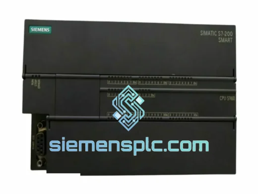
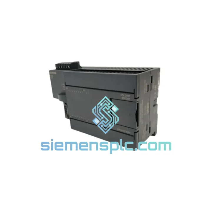
Siemens 6ES7214-2AD23-0XB0 PLC CPU Module – S7-200 SMART
Request verified availability, condition, replacement risk review, packing options and courier lead time for 6ES7214-2AD23-0XB0.
BrandSiemens
Part Number6ES7214-2AD23-0XB0
ConditionAvailability Check
Lead TimeRFQ Confirmation
DocumentsDatasheet / photos by RFQ
ShippingExport packing available
Auto-filled RFQ
6ES7214-2AD23-0XB0
Click Request Quote and the part number is inserted into the inquiry form automatically.
- Reply by email: [email protected]
- WhatsApp / Tel: +86 18359268345
- Mon-Sat 9:00-18:00 GMT+8
Procurement Data
Key Product Information
Core fields for model confirmation and RFQ routing. Detailed product narrative remains below.
- Brand
- Siemens
- Primary Part Number
- 6ES7214-2AD23-0XB0
- Product Type
- PLC CPU Module
- Series / Family
- SIMATIC
- Country of Origin
- DE
- Catalog Category
- Relays & Protection
- Operating Temp.
- 0 °C to +55 °C
- Warranty
- 12 months from date of dispatch
Model confirmed for inquiry
6ES7214-2AD23-0XB0
Send quantity, destination and urgency. The RFQ form keeps this part number attached.
Request Quote
Product Overview
Siemens 6ES7214-2AD23-0XB0 CPU SR20: AC-Powered Relay-Output Controller for Deterministic Machine Sequencing
The 6ES7214-2AD23-0XB0 is a fixed-I/O programmable logic controller within Siemens’ SIMATIC S7-200 SMART family. Designated CPU SR20, the “S” suffix identifies the AC mains power supply variant and the “R” suffix confirms relay-type digital outputs — a combination that directly eliminates two common BOM line items in panel design: a dedicated 24 VDC SMPS and interposing relay banks for inductive load switching. With 12 digital inputs at DC 24 V and 8 relay outputs rated at 2 A per point, the SR20 addresses the majority of discrete machine control tasks without any expansion hardware.
In the control loop hierarchy, the CPU SR20 occupies the machine-level controller position. It executes the user program cyclically, processes field sensor signals through its input image table, evaluates logic, and writes output states to actuators — all within a deterministic scan cycle. The onboard Ethernet port (RJ45, 10/100 Mbit/s) enables direct PROFINET-compatible communication with SIMATIC SMART LINE HMI panels and SCADA systems over standard TCP/IP infrastructure, without requiring a dedicated CP communication module.
The SR20 is deployed across packaging machinery, HVAC pump sequencing, conveyor indexing, injection moulding cycle control, water treatment dosing stations, and OEM compact machine builds where DIN rail space and panel cost are primary constraints. Its 90 × 100 × 81 mm footprint accommodates up to six EM-series signal expansion modules on the right-side local bus, allowing the base unit to scale from 20 I/O points to over 100 without changing the CPU.
Real-time Stock & RFQ: [email protected] | WhatsApp: +86 18359268345
Technical Parameters
| Parameter | Specification |
|---|---|
| Order Number | 6ES7214-2AD23-0XB0 |
| Series | SIMATIC S7-200 SMART |
| CPU Designation | CPU SR20 |
| Power Supply Input | AC 85–264 V, 47–63 Hz |
| Sensor Supply Output | DC 24 V / 300 mA (for field devices) |
| Digital Inputs (DI) | 12 × DC 24 V, sink/source compatible |
| Digital Outputs (DO) | 8 × Relay, 2 A per point, 10 A common |
| Program Memory | 24 KB |
| Data Memory | 10 KB (retentive via integrated EEPROM) |
| High-Speed Counters | 4 channels, up to 200 kHz |
| Pulse Train Outputs | Not applicable (relay output model) |
| Onboard Communication | 1 × Ethernet RJ45, 10/100 Mbit/s |
| Expansion Capability | Up to 6 × EM signal modules |
| Real-Time Clock | Integrated, battery-backed |
| Programming Environment | STEP 7-Micro/WIN SMART V2.x |
| Programming Languages | LAD, FBD, STL |
| Operating Temperature | 0 °C to +55 °C |
| Storage Temperature | −40 °C to +70 °C |
| Relative Humidity | 5–95%, non-condensing |
| Protection Class | IP20 (IEC 60529) |
| Mounting | 35 mm DIN rail (EN 60715) |
| Dimensions (W × H × D) | 90 × 100 × 81 mm |
| Weight | Approx. 500 g |
| Certifications | CE, UL, cULus, RCM, KC, IEC 61131-2 |
| Warranty | 12 months from date of dispatch |
Hardware Logical Analysis
The SR20’s input circuit architecture uses optocoupler isolation on all 12 digital input channels. Each input is galvanically separated from the CPU logic plane by a phototransistor stage rated for common-mode voltages up to 500 V peak, which suppresses conducted interference from inductive switching transients on shared cable runs — a frequent failure mode in relay-heavy panels. The input filter time is software-configurable per channel (0.2 ms to 12.8 ms), allowing the engineer to trade off noise rejection against response latency depending on whether the signal source is a mechanical limit switch (requiring debounce) or a proximity sensor (requiring fast response).
The relay output stage uses bifurcated gold-plated contacts on each of the 8 output points. Bifurcated contacts maintain reliable continuity at low-current signal loads (as low as 5 mA at 5 V DC) while retaining the 2 A switching capacity for 230 V AC contactor coils. The output commons are grouped into two independent commons, allowing mixed-voltage load circuits (e.g., 24 V DC solenoids on one group and 230 V AC contactors on another) within the same CPU without external isolation relays.
The CPU’s backplane bus is a proprietary high-speed serial interface that connects the base unit to EM expansion modules. Data exchange across this bus is synchronous with the CPU scan cycle — expansion module I/O images are updated in a single burst at the start of each scan, maintaining consistent I/O latency regardless of the number of attached modules. This deterministic update mechanism is critical in applications such as conveyor indexing, where a delayed output state could result in product misalignment.
EMC design on the SR20 follows IEC 61000-4 test levels for industrial environments. The PCB layout employs a split ground plane strategy: the analog reference ground and digital logic ground are connected at a single star point, preventing digital switching noise from coupling into analog measurement circuits when EM analog modules are attached. The housing is die-cast with conductive gaskets at all seams, providing a continuous Faraday enclosure that attenuates radiated emissions and external RF interference.
System Integration Benefits
- Elimination of External 24 V PSU: The AC power input (85–264 V) accepts mains voltage directly, removing the need for a separate switched-mode power supply in panels fed from single-phase or three-phase distribution. This reduces panel component count, wiring complexity, and potential failure points.
- Direct Inductive Load Switching: Relay outputs rated at 2 A / 250 V AC switch contactor coils, solenoid valves, and pilot lamps without interposing relays, reducing panel wiring density and eliminating relay coil suppression components.
- Native Ethernet for HMI and SCADA: The integrated 10/100 Mbit/s Ethernet port supports S7 communication protocol, enabling direct connection to SIMATIC SMART LINE panels and third-party SCADA systems over standard network infrastructure without additional CP modules.
- Scalable I/O Architecture: Six EM expansion slots allow the base 20-point I/O configuration to expand to analog inputs, RTD/thermocouple measurement, and additional digital I/O — all managed within a single STEP 7-Micro/WIN SMART project without hardware reconfiguration of the CPU.
- Configurable Input Filtering: Per-channel digital input filter times (0.2–12.8 ms) allow the same CPU to interface with both high-frequency proximity sensors and mechanically bouncing limit switches within the same program, without external filter hardware.
- Integrated Real-Time Clock: The battery-backed RTC enables time-stamped event logging, scheduled task execution (e.g., daily pump rotation), and production shift tracking directly within the CPU without an external timekeeping module.
- EEPROM-Backed Data Retention: Critical process parameters and counter values stored in retentive data memory survive power loss without a UPS, maintaining production state across unplanned shutdowns.
- Free Programming Software: STEP 7-Micro/WIN SMART is available at no cost from Siemens, with built-in motion control wizards, PID loop configuration tools, and Modbus RTU library — reducing software licensing overhead for OEM machine builders.
- Mixed-Voltage Output Grouping: Independent output commons allow simultaneous control of 24 V DC and 230 V AC loads from the same CPU output card, eliminating the need for separate relay modules for mixed-voltage applications.
- Compact DIN Rail Footprint: At 90 mm width, the SR20 occupies minimal horizontal DIN rail space, enabling high-density panel layouts in space-constrained enclosures typical of OEM machine builds.
Quality Assurance & Global Logistics
Every 6ES7214-2AD23-0XB0 unit supplied through siemensplc.com is sourced as genuine Siemens factory-sealed product. Prior to dispatch from our Xiamen, China facility, each unit undergoes a structured pre-shipment inspection protocol:
- Label and order number verification against Siemens product database
- Housing and connector integrity check (no mechanical damage, pin deformation, or seal compromise)
- Firmware version confirmation against current Siemens release documentation
- Power-on functional test under STEP 7-Micro/WIN SMART
- Anti-static bag sealing with humidity indicator card
- Original Siemens factory carton with documentation pack
Shipments are dispatched from Xiamen via DHL Express, FedEx International Priority, and UCP air freight, with typical transit times of 3–7 business days to Europe, North America, Southeast Asia, and the Middle East. All shipments include tracking, commercial invoice, and packing list. Export documentation for customs clearance is prepared in compliance with HS Code 8537.10 classification. A 12-month warranty against manufacturing defects applies to all units from the date of dispatch.
Contact Information
Email: [email protected]
WhatsApp: +86 18359268345
Web: siemensplc.com
Location: Xiamen, China
© 2026 siemensplc.com. All rights reserved.
Ready to quote
[email protected]
Send This Part Number to Sales
RFQ workflow
Quality workflow ->
Confirmation Process
01Model confirmation
We check the full part number, brand, series and visible nameplate information before quotation.
02Availability reply
Sales confirms stock path, condition option, quantity and realistic lead time for export dispatch.
03Packing & courier
DHL, FedEx, UPS or buyer courier arrangements can be reviewed with packing requirements.
Continue sourcing
Browse full catalog ->
Related Automation Parts
Similar brand or category products for fast comparison and multi-item RFQ lists.
Siemens
RFQ Ready
SIEMENS 6ES7214-1HG40-0XB0 PLC CPU Module
SIMATIC S7-1200
Origin DE
PLC CPU Module