Siemens
RFQ Ready
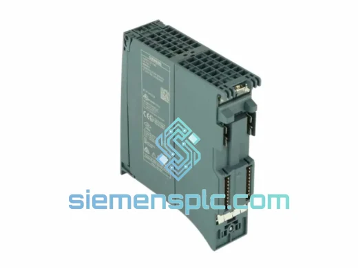
SIEMENS 6GK5108-0BA00-2AA3 Industrial Ethernet Switch
SIMATIC
Origin DE
Industrial Ethernet Switch
Request verified availability, condition, replacement risk review, packing options and courier lead time for 6GK1905-0AE00.
Click Request Quote and the part number is inserted into the inquiry form automatically.
Core fields for model confirmation and RFQ routing. Detailed product narrative remains below.
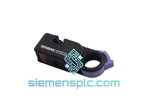
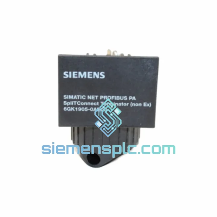
The 6GK1905-0AE00 is a passive PROFIBUS DP bus connector produced by Siemens AG within the SIMATIC NET communication hardware portfolio. Its primary function is to terminate the physical RS-485 differential bus at segment endpoints while simultaneously providing a mechanically compact, 90°-axial cable exit suited to panel-mounted field devices and marshalling cabinets with restricted depth clearance. The connector mates to standard 9-pin Sub-D (DB9) female ports and accommodates PROFIBUS Type A shielded twisted-pair cable with conductor cross-sections between 0.22 mm² and 0.5 mm².
In any RS-485 segment operating above 1.5 Mbit/s, unterminated endpoints generate standing-wave reflections whose amplitude is proportional to the impedance mismatch between the cable’s characteristic impedance and the load presented at the physical end of the conductor. At 12 Mbit/s — the maximum PROFIBUS DP baud rate — the bit period is 83 ns. A reflection with a round-trip propagation delay exceeding 40 ns will corrupt the trailing edge of the preceding bit, producing inter-symbol interference that the receiver’s comparator cannot resolve. The 6GK1905-0AE00 eliminates this failure mode by placing a precision resistor network directly at the DB9 mating interface, absorbing incident wave energy before it can reflect back toward the master.
Real-time Stock & RFQ: [email protected] | WhatsApp: +86 18359268345
| Parameter | Specification |
|---|---|
| Siemens Order Number | 6GK1905-0AE00 |
| Product Line | SIMATIC NET PROFIBUS |
| Connector Type | 9-pin Sub-D (DB9), female socket |
| Cable Exit Geometry | 90° axial (parallel to mating axis) |
| Supported Protocol | PROFIBUS DP V0 / V1 / V2 per IEC 61158 / EN 50170 |
| Physical Layer | RS-485 differential, half-duplex |
| Baud Rate Range | 9.6 kbit/s — 12 Mbit/s (all standard rates) |
| Termination Network | 390 Ω (VP pull-up) / 220 Ω (differential) / 390 Ω (DGND pull-down), slide-switch selectable |
| Idle Bus Bias | Defined logic-1 state (A > B) when termination ON |
| Applicable Cable | PROFIBUS Type A: 135–165 Ω characteristic impedance, ≤30 pF/m capacitance |
| Conductor Cross-Section | 0.22 mm² to 0.5 mm² |
| Wiring Interface | Screw terminal, color-coded per EN 50170 pin map |
| Operating Temperature | −40 °C to +85 °C |
| Storage Temperature | −40 °C to +85 °C |
| Degree of Protection | IP20 (connector body) |
| Housing Material | Flame-retardant thermoplastic, UL 94 V-0 rated |
| Panel Retention | UNC 4-40 jack screws (standard DB9 pattern) |
| Approximate Weight | 50 g |
| Compliance | CE, EN 50170, IEC 61158, RoHS |
| Country of Origin | Germany |
| Warranty | 12 months from confirmed shipment date |
Termination Resistor Network — Impedance Matching Mechanics
The three-resistor ladder inside the 6GK1905-0AE00 serves two distinct electrical functions simultaneously. The 220 Ω differential element provides a load impedance that approximates the cable’s characteristic impedance at high frequencies, suppressing the reflection coefficient at the segment endpoint. The 390 Ω pull-up to VP (+5 V bus supply) and 390 Ω pull-down to DGND bias the A and B lines to a defined differential voltage of approximately +0.9 V when no driver is active. This idle-state bias is mandatory in multi-master PROFIBUS configurations: without it, the bus floats to an indeterminate state during inter-frame gaps, and the first receiver to sample the line may interpret noise as a start bit, triggering a spurious frame reception that corrupts the token rotation sequence. The slide switch on the connector body connects or disconnects the entire network with a single mechanical action, eliminating the risk of partial termination caused by incorrect jumper placement.
EMC Architecture — Shield Termination Path
The connector housing is constructed from metallized thermoplastic or zinc-alloy shell (depending on production batch), providing a continuous conductive enclosure around the DB9 signal pins. The cable shield is clamped to the connector body via a dedicated strain-relief clamp, establishing a low-impedance bond between the cable’s outer foil/braid and the device chassis ground through the DB9 mounting screws. This path presents an impedance of typically <0.1 Ω at DC and <1 Ω at 10 MHz, which is sufficient to divert common-mode interference currents away from the differential signal pair. In installations adjacent to variable-frequency drives with switching frequencies of 4–16 kHz and dV/dt values exceeding 5 kV/μs, this shield continuity is the primary mechanism preventing induced noise from exceeding the RS-485 receiver’s common-mode rejection threshold of ±7 V.
90° Axial Exit — Mechanical Constraint Analysis
The cable exits the connector body parallel to the DB9 mating axis rather than at a right angle to it. This geometry reduces the connector’s protrusion depth from the device face to approximately 30–35 mm, compared to 60–80 mm for angled-exit variants. In marshalling cabinets where PROFIBUS slaves are mounted on DIN rail at 50 mm vertical pitch, the axial exit allows cable routing along the device face without exceeding the minimum bend radius of PROFIBUS Type A cable (5× outer diameter, typically 25–30 mm for 8 mm OD cable). Exceeding this bend radius increases conductor fatigue and degrades the cable’s characteristic impedance uniformity, introducing distributed reflections that are difficult to localize with standard bus analyzers.
Screw Terminal Design — Field Wiring Reliability
The internal screw terminals are labeled and color-coded per EN 50170 pin assignments: pin 3 (B-line, red), pin 8 (A-line, green), pin 5 (DGND, blue), pin 6 (VP, orange). This labeling eliminates the most common PROFIBUS commissioning error — A/B line reversal — which produces a valid electrical connection but inverts the differential signal polarity, causing all devices on the segment to fail to detect valid start bits. The terminals accept conductors without ferrules, reducing field assembly time by approximately 30 seconds per connection compared to ferrule-required designs.
All 6GK1905-0AE00 units dispatched from siemensplc.com originate from traceable Siemens-authorized supply channels or documented OEM surplus inventory with verifiable production date codes. Each unit is inspected prior to shipment for housing integrity, DB9 pin geometry, termination switch mechanical function, and shield clamp condition. Siemens original packaging is retained where available; otherwise, anti-static polyethylene bags with silica gel desiccant are used to prevent moisture absorption during ocean or air transit.
Batch lot records are maintained and cross-referenced to Siemens production date codes, enabling issuance of a Certificate of Conformance (CoC) for regulated-industry procurement requirements in pharmaceutical, water treatment, power generation, and defense sectors. Shipments originate from our facility in Xiamen, China, with direct access to DHL Express, FedEx International Priority, and UPS Worldwide Express networks. Typical transit times are 3–5 business days to Europe, 4–6 days to North America, and 2–4 days to Southeast Asia. For volume orders exceeding 50 units, sea freight consolidation with full export documentation — commercial invoice, packing list, certificate of origin, and packing declaration — is available on request.
A 12-month warranty from the confirmed shipment date covers manufacturing defects in materials and workmanship. Pre-sales technical support — including PROFIBUS segment design review, baud rate selection guidance, cable specification, and termination placement verification — is provided at no charge by our engineering team prior to order placement.
Email: [email protected]
WhatsApp: +86 18359268345
Web: siemensplc.com
Location: Xiamen, China
© 2026 siemensplc.com. All rights reserved.
We check the full part number, brand, series and visible nameplate information before quotation.
Sales confirms stock path, condition option, quantity and realistic lead time for export dispatch.
DHL, FedEx, UPS or buyer courier arrangements can be reviewed with packing requirements.
Similar brand or category products for fast comparison and multi-item RFQ lists.