Siemens
In Stock OK
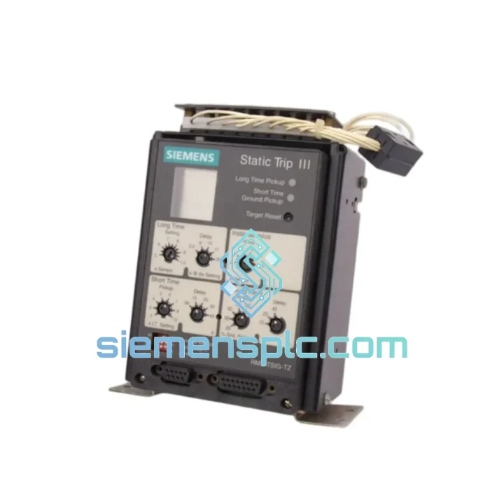
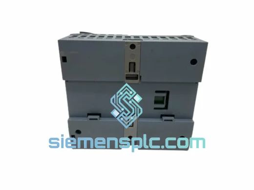
Siemens RMS-TSIG-TZ-C Electronic Trip Unit – SENTRON 3WL Series
Request verified availability, condition, replacement risk review, packing options and courier lead time for RMS-TSIG-TZ-C.
BrandSiemens
Part NumberRMS-TSIG-TZ-C
ConditionAvailability Check
Lead TimeRFQ Confirmation
DocumentsDatasheet / photos by RFQ
ShippingExport packing available
Auto-filled RFQ
RMS-TSIG-TZ-C
Click Request Quote and the part number is inserted into the inquiry form automatically.
- Reply by email: [email protected]
- WhatsApp / Tel: +86 18359268345
- Mon-Sat 9:00-18:00 GMT+8
Procurement Data
Key Product Information
Core fields for model confirmation and RFQ routing. Detailed product narrative remains below.
- Brand
- Siemens
- Primary Part Number
- RMS-TSIG-TZ-C
- Product Type
- Electronic Trip Unit
- Product Family
- Other series
- Manufacturer
- Siemens AG
- Country of Origin
- DE
- Catalog Category
- Relays & Protection
- Operating Temp.
- −25 °C to +70 °C
- Warranty
- 12 months from date of dispatch
Model confirmed for inquiry
RMS-TSIG-TZ-C
Send quantity, destination and urgency. The RFQ form keeps this part number attached.
Request Quote
Product Overview
Siemens RMS-TSIG-TZ-C: Solid-State Overcurrent Release with Zone-Selective Interlock for SENTRON 3WL Air Circuit Breakers
The Siemens RMS-TSIG-TZ-C is a microprocessor-based electronic trip unit (ETU) engineered for integration into the Siemens SENTRON 3WL series air circuit breakers. Unlike conventional thermal-magnetic releases, this module executes overcurrent protection through a dedicated signal-processing chain: current transformers feed analog signals into a precision rectifier and RMS-conversion circuit, which the onboard microcontroller evaluates against independently configurable thresholds for long-time (L), short-time (S), instantaneous (I), and ground-fault (G) protection functions. The TZ-C suffix designates the variant equipped with Zone-Selective Interlock (ZSI) output and communication capability, enabling coordinated fault isolation across multi-tier switchgear architectures without sacrificing selectivity margins.
In a typical medium-voltage/low-voltage substation feeding a process plant, the RMS-TSIG-TZ-C operates as the primary decision node in the protection hierarchy. When a downstream fault occurs, the module’s ZSI bus transmits a restraint signal to the upstream incomer breaker, instructing it to extend its short-time delay while the feeder breaker clears the fault at minimum trip time. This mechanism eliminates the need for wide time-grading margins, preserving upstream supply continuity and reducing arc-flash incident energy at the fault point — a measurable safety and operational benefit in facilities operating under NFPA 70E or IEC 62271-200 frameworks.
Real-time Stock & RFQ: [email protected] | WhatsApp: +86 18359268345
Technical Parameters
| Parameter | Value / Specification |
|---|---|
| Manufacturer | Siemens AG |
| Part Number | RMS-TSIG-TZ-C |
| Module Classification | Electronic Trip Unit (ETU) — Static Overcurrent Release |
| Host Breaker Platform | Siemens SENTRON 3WL Air Circuit Breaker (Frame 1–4) |
| Rated Current Coverage | 630 A – 6300 A (frame-dependent) |
| Protection Functions | L (Long-time), S (Short-time), I (Instantaneous), G (Ground-fault) |
| Measurement Method | True RMS via dedicated current transformer inputs |
| ZSI Capability | Yes — Zone-Selective Interlock output/input (TZ-C suffix) |
| Communication Interface | Integrated (C suffix) — compatible with PROFIBUS DP / PROFINET IO via communication module |
| Mounting Method | Plug-in, front-panel integrated into 3WL breaker housing |
| Operating Temperature | −25 °C to +70 °C |
| Storage Temperature | −40 °C to +85 °C |
| Degree of Protection | IP54 (within breaker enclosure) |
| Applicable Standards | IEC 60947-2, EN 60947-2, UL 489 (where applicable) |
| Auxiliary Supply | Self-powered from current transformer loop; auxiliary supply for communication functions |
| Weight (unit) | Approx. 1,600 g (including OEM packaging) |
| Country of Origin | Germany |
| Warranty | 12 months from date of dispatch |
Hardware Logical Analysis
The RMS-TSIG-TZ-C is built around a three-layer hardware architecture that separates signal acquisition, protection logic execution, and output actuation into discrete functional blocks — a design philosophy that directly improves both measurement accuracy and fault response determinism.
Signal Acquisition Layer: Each phase current and the neutral conductor are monitored by dedicated toroidal current transformers embedded in the breaker’s current path. The secondary outputs feed into a precision full-wave rectifier and true-RMS conversion circuit. Unlike average-responding designs, true-RMS measurement correctly evaluates non-sinusoidal load currents — a critical requirement in facilities with variable-frequency drives (VFDs), UPS systems, or arc furnaces where harmonic content can reach 30–40% THD. Measurement error under these conditions is held within ±2% across the rated current range.
Protection Logic Execution Layer: The microcontroller continuously compares the RMS-converted current values against independently configurable thresholds for each protection function. The long-time (L) function uses an inverse-time characteristic modeled on IEC 60255-151 curves, accumulating thermal memory across load cycles. The short-time (S) function applies a definite-time delay (configurable from 0.1 s to 0.5 s) with an optional I²t ramp-off, allowing the downstream protection to operate first. The instantaneous (I) function bypasses all delays and triggers direct trip actuation within one half-cycle (<10 ms) when fault current exceeds the set threshold — typically 2–15× In. The ground-fault (G) function monitors residual current via a vectorial summation of phase and neutral CT outputs, with sensitivity adjustable to detect leakage currents as low as 20% of rated current.
EMC Design and Noise Immunity: The module’s PCB layout employs ground-plane partitioning to isolate the analog signal path from the digital processing domain. Transient suppression diodes (TVS) are placed at all external interface connectors, and the ZSI bus interface includes optical isolation to prevent ground-loop coupling between breakers at different potential levels. Conducted and radiated emission compliance is verified to EN 55011 Class A, and immunity is tested per IEC 61000-4-2 (ESD, 8 kV contact), IEC 61000-4-4 (EFT, 4 kV), and IEC 61000-4-5 (surge, 2 kV line-to-earth) — performance levels consistent with heavy industrial switchgear environments.
ZSI Interlock Logic: The zone-selective interlock operates on a two-wire bus connecting all breakers in a protection zone. When the RMS-TSIG-TZ-C detects a fault current exceeding the short-time threshold, it simultaneously initiates its own S-function delay and asserts a restraint signal on the ZSI bus. Upstream breakers receiving this signal extend their own S-function delay, ensuring the downstream device clears the fault first. If the downstream breaker fails to clear within the configured delay window, the upstream breaker trips unconditionally. This logic is implemented in hardware-assisted firmware with a response latency of less than 2 ms — fast enough to maintain selectivity even at high fault current magnitudes where thermal stress accumulates rapidly.
System Integration Benefits
- Deterministic Protection Coordination: The ZSI mechanism eliminates the need for wide time-grading margins between upstream and downstream breakers. In a conventional graded scheme, the incomer may carry a 0.4 s delay to allow a 0.2 s feeder to clear; with ZSI, the incomer delay is only activated when the feeder fails, reducing arc-flash exposure time at the fault point by up to 80% in coordinated topologies.
- True-RMS Measurement Accuracy: Correct evaluation of distorted load currents prevents nuisance tripping on harmonic-rich loads (VFDs, rectifiers, welding equipment) while maintaining sensitivity to genuine overcurrent events. This directly reduces unplanned downtime caused by false trips.
- Thermal Memory Retention: The long-time protection function retains accumulated thermal state across power cycles, preventing repeated overloading of cables and busbars that would otherwise go undetected after a brief supply interruption.
- Integrated Ground-Fault Protection: Eliminates the need for a separate residual current device (RCD) or ground-fault relay in the feeder circuit, reducing panel footprint and simplifying the protection coordination study.
- PROFIBUS/PROFINET Diagnostics: The communication interface (C suffix) exposes real-time current values, trip cause codes, and protection parameter settings to the plant DCS or SCADA system. Maintenance teams can read trip logs and adjust protection settings remotely without opening the switchgear panel — a significant safety advantage in energized environments.
- Plug-in Replacement Architecture: The module connects to the 3WL breaker via a keyed multi-pin connector that prevents incorrect insertion. Replacement in the field requires no rewiring and no recalibration of the current transformer secondary circuit, reducing mean time to repair (MTTR) to under 30 minutes for a trained technician.
- Self-Monitoring and Fault Diagnostics: The onboard firmware executes a continuous self-test routine covering CT input continuity, microcontroller watchdog, and trip coil circuit integrity. Any detected hardware fault generates a diagnostic alarm via the communication interface and activates a local LED indicator, enabling predictive maintenance before a protection failure occurs.
- Selective Coordination Compliance: The combination of configurable S-function delay, I²t characteristic, and ZSI support allows the RMS-TSIG-TZ-C to satisfy selective coordination requirements per NEC 2023 Article 700 and IEC 60364-5-53, which mandate that only the faulted circuit is de-energized in critical power distribution systems (hospitals, data centers, emergency lighting).
Quality Assurance & Global Logistics
Every RMS-TSIG-TZ-C unit supplied by siemensplc.com is sourced as genuine Siemens OEM product through verified industrial supply channels. Each unit is inspected against a four-point protocol before dispatch: physical and label authenticity verification, connector and housing integrity check, functional power-on test where applicable, and documentation cross-reference against Siemens factory records including date code and country of origin.
Available documentation on request includes Certificate of Conformity (CoC), factory test report, Material Safety Data Sheet (MSDS), and full export/customs documentation for international shipments. Anti-static packaging with tamper-evident sealing is standard for all units.
Logistics operations are based in Xiamen, China, with established freight partnerships covering DHL Express, FedEx International Priority, and sea freight consolidation for bulk orders. Typical transit times: 3–5 business days to Europe and North America via express courier; 7–12 business days via standard air freight. Export documentation including commercial invoice, packing list, and HS code declaration (HS 8536.49) is prepared for all international shipments. Emergency same-day dispatch is available for in-stock units when orders are confirmed before 14:00 CST.
Contact Information
Email: [email protected]
WhatsApp: +86 18359268345
Web: siemensplc.com
Location: Xiamen, China
© 2026 siemensplc.com. All rights reserved.
Ready to quote
[email protected]
Send This Part Number to Sales
RFQ workflow
Quality workflow ->
Confirmation Process
01Model confirmation
We check the full part number, brand, series and visible nameplate information before quotation.
02Availability reply
Sales confirms stock path, condition option, quantity and realistic lead time for export dispatch.
03Packing & courier
DHL, FedEx, UPS or buyer courier arrangements can be reviewed with packing requirements.
Continue sourcing
Browse full catalog ->
Related Automation Parts
Similar brand or category products for fast comparison and multi-item RFQ lists.
Siemens
RFQ Ready
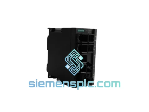
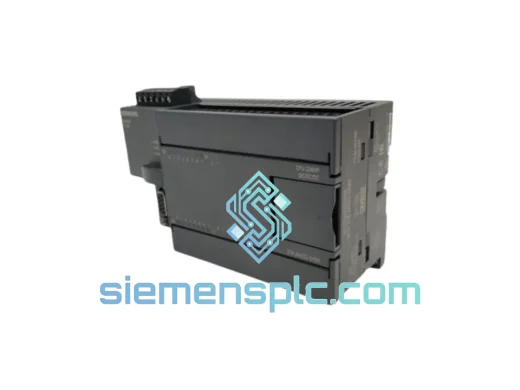
Siemens 6ES7214-2AD23-0XB0 PLC CPU Module – S7-200 SMART
SIMATIC
Origin DE
PLC CPU Module
Siemens
RFQ Ready
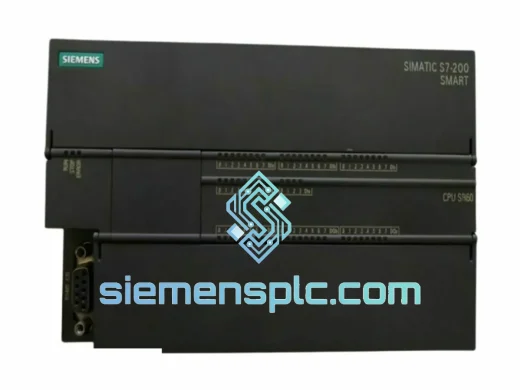
SIEMENS 6ES7214-1HG40-0XB0 PLC CPU Module
SIMATIC S7-1200
Origin DE
PLC CPU Module