TRICONEX
RFQ Ready
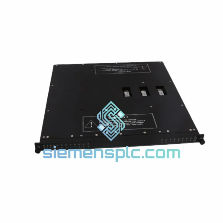
TRICONEX 9563-810 Safety Termination Panel
Tricon
Origin US
Safety System Termination Panel
Request verified availability, condition, replacement risk review, packing options and courier lead time for 3603T.
Click Request Quote and the part number is inserted into the inquiry form automatically.
Core fields for model confirmation and RFQ routing. Detailed product narrative remains below.
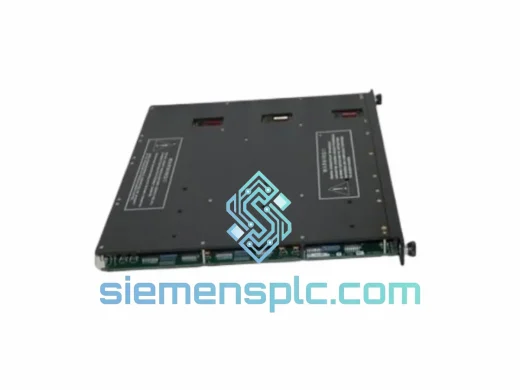
The TRICONEX 3603T is a 32-channel, 24 VDC solid-state digital output (DO) module purpose-built for the Tricon Triple Modular Redundant (TMR) Safety Instrumented System. It occupies a single slot in any Tricon 8-slot or 16-slot main chassis or expansion chassis and interfaces with the Tricon Main Processor (MP) via the proprietary TMR backplane bus. The module is rated for deployment in Safety Instrumented Functions (SIFs) requiring IEC 61508 SIL 3 integrity and is fully compliant with the IEC 61511 functional safety lifecycle for the process industries.
Each of the 32 output channels is implemented across three independent solid-state driver circuits — one per TMR leg (Leg A, Leg B, Leg C). The three driver states are resolved by a hardware 2-out-of-3 (2oo3) voter before the switching signal reaches the field terminal. Output state is therefore determined by majority agreement among three independent hardware paths, not by software arbitration. This structural separation is architecturally necessary for SIL 3 compliance under IEC 61508 Part 2, where common-cause software failures must be excluded from the safety function’s fault tolerance calculation.
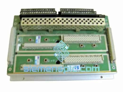
Field wiring connects through the Tricon Terminal Panel (TP) associated with the module’s chassis slot. The TP provides screw-terminal or marshalling-panel connectivity to field devices operating at 24 VDC — solenoid valve coils, relay coils, motor starter contactors, and discrete indicator lamps. The solid-state sourcing output topology eliminates mechanical contact wear, reduces scheduled maintenance intervals, and delivers sub-millisecond switching response times relative to relay-based output modules. Per-channel electronic short-circuit protection prevents a field wiring fault from propagating damage to adjacent channels or to the module’s internal power distribution rail.
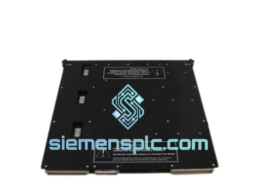
Hot-swap capability is a standard operational feature of the Tricon platform. The 3603T can be extracted and reinserted into a live chassis without requiring a system shutdown or a process trip, provided that site-specific Safe Work Procedures (SWP) and Management of Change (MOC) protocols are observed. During a hot-swap event, the remaining two TMR legs maintain the output state through the 2oo3 voting mechanism, preserving process continuity. This characteristic is particularly significant for continuous-process facilities — refineries, LNG terminals, ethylene crackers, and chemical plants — where planned shutdown windows are measured in years rather than months.
The 3603T is backward-compatible with earlier 3600-series digital output modules in existing certified Tricon architectures. Substitution does not require re-engineering of the safety case or modification of the application logic, provided the replacement module carries the same part number and revision level as the module being replaced. This compatibility profile makes the 3603T the standard procurement specification for Tricon I/O rack expansions and aging-module replacement programs across the global installed base of Tricon TMR systems.
Procurement lead times for the 3603T from standard distribution channels can extend to 16–26 weeks during periods of high demand. siemensplc.com maintains verified stock of genuine TRICONEX 3603T modules sourced from authorized distributors and documented surplus channels, enabling same-week shipment from Xiamen, China to industrial facilities worldwide. Each unit is inspected, tested, and shipped with full documentation prior to dispatch.
Real-time Stock & RFQ: [email protected] | WhatsApp: +86 18359268345
| Parameter | Specification |
|---|---|
| Part Number | 3603T |
| Module Classification | Digital Output (DO), Solid-State Sourcing |
| Platform Compatibility | TRICONEX Tricon TMR Safety System (8-slot / 16-slot chassis) |
| Output Channel Count | 32 discrete channels, individually addressable |
| Nominal Output Voltage | 24 VDC (field-side) |
| Output Switching Topology | Solid-state NPN/PNP sourcing transistor per channel per leg |
| Maximum Load Current | 0.5 A per channel (derate per chassis thermal load calculation) |
| Short-Circuit Protection | Per-channel electronic current limiting; fault isolated to affected channel |
| Redundancy Architecture | Triple Modular Redundant (TMR) — hardware 2oo3 voting per channel |
| Safety Integrity Level | SIL 3 capable — IEC 61508 Ed.2 / IEC 61511 Ed.2 |
| Fault Tolerance | Single fault tolerant; two-leg operation maintained on one-leg failure |
| Diagnostic Coverage (DC) | High (≥ 99%) — continuous per-channel closed-loop self-test every scan cycle |
| Backplane Interface | Tricon proprietary TMR backplane bus (command + diagnostic return path) |
| Optical Isolation | Optocoupler isolation at backplane/field boundary; ≥ 500 V galvanic isolation |
| Hot-Swap Support | Yes — online module replacement without system shutdown |
| Output Switching Latency | Bounded by MP scan cycle (configurable, deterministic) |
| Operating Temperature | 0 °C to +60 °C |
| Storage Temperature | −40 °C to +85 °C |
| Relative Humidity | 5% to 95%, non-condensing |
| Form Factor | Single-slot Tricon I/O module |
| Module Weight | Approx. 500 g (module only, excluding terminal panel) |
| Chassis Power Draw | Via Tricon backplane power bus (redundant PSU-fed) |
| Warranty | 12 months against manufacturing defects from date of shipment |
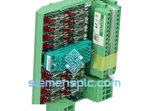
Three-Leg Independent Driver Architecture: The 3603T implements each output channel as three physically separate solid-state driver circuits, one per TMR leg. Each driver receives its switching command independently from its respective leg processor over the backplane bus. The three driver output states are fed into a discrete hardware 2oo3 voter circuit before the field terminal. The voter’s output — not any individual leg’s output — drives the field device. This means a single transistor failure, a single backplane trace open-circuit, or a single leg processor fault cannot unilaterally change the field-side switching state. The safety function remains intact with one leg failed, and the failure is annunciated to the operator without interrupting the output.
Optocoupler Isolation Boundary: At the interface between the backplane logic domain (3.3 V / 5 V CMOS) and the field-side driver domain (24 VDC), the 3603T inserts an optocoupler isolation stage on each channel. This galvanic barrier provides a minimum 500 V isolation rating, blocking conducted transients generated by inductive field loads. Solenoid valve coils, when de-energized, produce voltage spikes of 10× to 50× the supply voltage. Without the optocoupler stage, these transients would propagate into the backplane logic and degrade the module’s MTBF. The isolation stage also prevents ground loop currents between the field wiring ground and the chassis logic ground from introducing noise into the backplane bus.
EMC Hardening and Transient Suppression: The module’s PCB layout follows IEC 61000-4 series EMC design rules. Transient voltage suppression (TVS) diodes are placed at each output terminal to clamp inductive kickback below the output transistor’s breakdown voltage. The backplane connector and field-side terminal interface are routed on separate PCB layers with an interposed ground plane, reducing capacitive coupling of high-frequency noise from field cables into the backplane bus. The module housing maintains shielding continuity with the Tricon chassis ground, forming a Faraday enclosure around the internal electronics. Conducted and radiated immunity is verified to IEC 61000-4-2 (ESD), IEC 61000-4-4 (EFT), and IEC 61000-4-5 (surge) test levels.
Closed-Loop Per-Channel Diagnostic Feedback: Each output channel includes a feedback sense circuit that reads the actual switching state of the output transistor and returns this value to the leg processor on every scan cycle. The processor compares the commanded state against the sensed state. A mismatch — indicating a failed-open or failed-closed transistor — is logged as a channel-level fault in the MP’s diagnostic register within one scan cycle (typically 10–100 ms depending on MP configuration). This closed-loop architecture achieves the high diagnostic coverage (DC ≥ 99%) required for SIL 3 hardware fault tolerance calculations under IEC 61508 Part 2, Table 3.
Thermal Management and Power Architecture: The 3603T draws operating power from the Tricon chassis backplane power bus, which is fed by redundant power supply modules. An internal DC-DC converter provides regulated voltages to the logic and driver circuits, with overcurrent protection on each internal rail. Thermal dissipation is conducted through the module’s aluminum faceplate to the chassis frame. The 0 °C to +60 °C operating range is specified to account for the thermal rise within a fully populated chassis under maximum aggregate load current conditions, ensuring no derating is required in standard industrial enclosure installations.
Every TRICONEX 3603T unit supplied by siemensplc.com is sourced from authorized distribution channels or verified surplus inventories with documented chain of custody. Prior to shipment, each module undergoes a structured incoming inspection protocol: visual examination of the module housing and faceplate for physical damage; label verification confirming part number (3603T), revision level, and serial number against manufacturer documentation; and a functional bench-test verifying backplane connector pin integrity and output driver continuity across all 32 channels.
Modules are packaged in IEC 61340-5-1 compliant ESD-protective anti-static bags, enclosed in foam-lined corrugated cartons with moisture barrier film. This packaging specification meets IPC/JEDEC J-STD-033 handling requirements for moisture-sensitive electronic assemblies and protects the module against electrostatic discharge, mechanical shock, and humidity ingress during international transit.
Shipments originate from Xiamen, China via DHL Express, FedEx International Priority, and UPS Worldwide Express. Indicative transit times: 3–5 business days to Southeast Asia; 5–7 business days to Europe and the Middle East; 5–8 business days to North America and Australia. Full export documentation — commercial invoice, packing list, and applicable export classification records — is prepared for each shipment to facilitate customs clearance at the destination port. A 12-month replacement warranty against manufacturing defects is provided with each unit. Certificate of Conformance (CoC) and incoming inspection test report are available upon request at time of order placement.
Email: [email protected]
WhatsApp: +86 18359268345
Web: siemensplc.com
Location: Xiamen, China
© 2026 siemensplc.com. All rights reserved.
We check the full part number, brand, series and visible nameplate information before quotation.
Sales confirms stock path, condition option, quantity and realistic lead time for export dispatch.
DHL, FedEx, UPS or buyer courier arrangements can be reviewed with packing requirements.
Similar brand or category products for fast comparison and multi-item RFQ lists.