TRICONEX
RFQ Ready
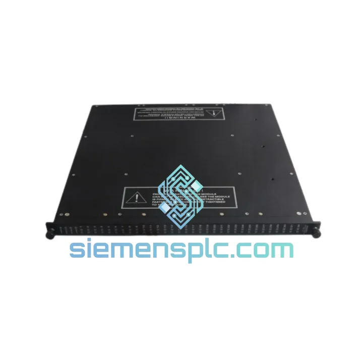
TRICONEX 9563-810 Safety Termination Panel
Tricon
Origin US
Safety System Termination Panel
Request verified availability, condition, replacement risk review, packing options and courier lead time for 9760-210.
Click Request Quote and the part number is inserted into the inquiry form automatically.
Core fields for model confirmation and RFQ routing. Detailed product narrative remains below.
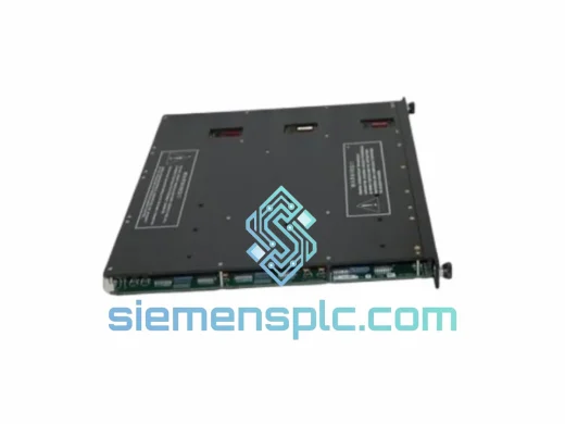
The TRICONEX 9760-210 is a dedicated Digital Input Termination Panel engineered to serve as the physical and electrical demarcation point between field-side discrete signal conductors and the three independent input legs of a Tricon Triple Modular Redundant (TMR) safety controller. In any SIL 3 safety instrumented function (SIF), the quality of the field-wiring interface is not incidental — it is a load-bearing element of the overall fault-tolerance architecture. The 9760-210 defines where field conductors terminate, how signals are distributed across the TMR channel matrix, and where the creepage and clearance boundaries required by IEC 60664-1 are physically enforced.
This panel mates directly with Triconex digital input modules installed in Tricon v9, v10, and v11 chassis configurations. Its screw-clamp terminal array provides a deterministic, labeled wiring interface that maps each field conductor to a specific position in the module’s three-leg input structure. In process safety applications — ESD systems, fire and gas detection loops, turbine trip circuits — the 9760-210 is a traceable hardware component within the functional safety assessment boundary and must be documented by part number and revision in the safety case file.
Real-time Stock & RFQ: [email protected] | WhatsApp: +86 18359268345
| Parameter | Specification |
|---|---|
| Part Number | 9760-210 |
| Manufacturer | TRICONEX (Schneider Electric Safety Systems) |
| Panel Classification | Digital Input Termination Panel (DI) |
| Compatible Platform | Tricon TMR Chassis — v9, v10, v11 series |
| TMR Architecture | Triple Modular Redundant, 3-leg independent channel routing |
| Safety Integrity Level | SIL 3 (IEC 61508 / IEC 61511 compliant system boundary) |
| Field Signal Type | Discrete dry-contact or 24 VDC sourcing/sinking inputs |
| Terminal Interface | Screw-clamp terminal blocks, field-side conductor termination |
| Module Connector | Dedicated direct connector, revision-controlled mating interface |
| Operating Temperature | 0 °C to +60 °C |
| Storage Temperature | −40 °C to +85 °C |
| Relative Humidity | 5% to 95%, non-condensing |
| Vibration Standard | IEC 60068-2-6 (sinusoidal sweep), IEC 60068-2-64 (broadband random) |
| Mounting Configuration | Panel-mount, Tricon marshalling enclosure |
| Unit Weight | Approx. 2,320 g |
| Country of Origin | USA (TRICONEX manufacturing) |
| Warranty | 12 months from shipment date |
| Availability | In Stock — Ready for immediate dispatch from Xiamen, China |
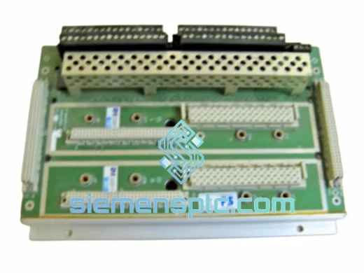
Three-leg signal distribution at the termination boundary: The 9760-210’s internal conductor matrix performs a function that is architecturally critical but often underappreciated: it takes a single field signal — one contact closure, one 24 VDC assertion — and routes it simultaneously to three electrically independent terminal positions on the module connector. These three positions feed Leg A, Leg B, and Leg C of the mating Tricon DI module. Each leg processes the signal through its own optocoupler isolation stage, its own analog-to-digital conversion path, and its own dedicated microprocessor. The TMR voter compares the three resulting digital states and outputs the 2-of-3 majority result. For this architecture to deliver its certified fault tolerance, the three signal paths must remain electrically independent from the field terminal block through to the optocoupler input — the 9760-210’s PCB trace geometry and terminal block spacing are designed to maintain this independence under the voltage and current conditions present in industrial field wiring environments.
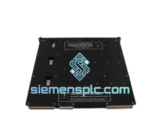
Creepage and clearance enforcement: Field-side wiring in process plant environments carries voltage potentials that differ from the Tricon backplane reference by amounts that vary with grounding topology, cable routing, and proximity to power equipment. The 9760-210’s PCB layout maintains the creepage distances specified by IEC 60664-1 for the applicable overvoltage category and pollution degree. This is not a passive design choice — it is a quantified electrical safety requirement that prevents surface tracking between conductors at different potentials under the humidity and contamination conditions present in marshalling cabinet environments over a 20-year service life.
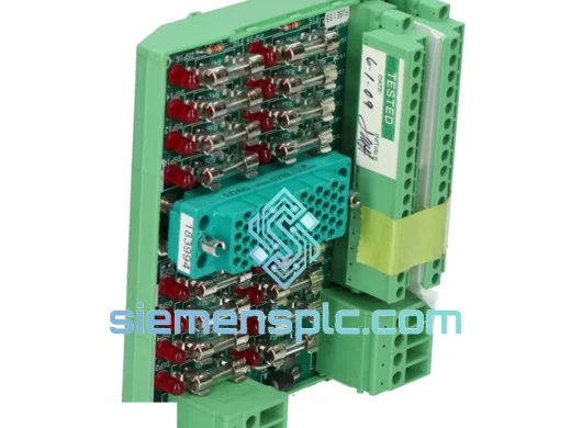
EMC boundary behavior: The termination panel sits at the interface between the uncontrolled electromagnetic environment of the field cable tray and the controlled environment of the Tricon chassis. Inductive transients from solenoid valve coils, ground loop currents from geographically separated field instruments, and conducted interference from variable frequency drives in adjacent panels all arrive at the 9760-210 terminal blocks before reaching the DI module’s optocoupler isolation stage. The panel’s terminal block layout, combined with Triconex’s field wiring guidelines for shielded cable termination and shield grounding, defines the first line of EMC attenuation in the signal chain. Compliance with these guidelines is part of the system-level EMC validation documented in the Tricon installation manual.
Revision control and connector compatibility: Triconex has maintained revision control over the 9760-210 and its associated DI modules across the Tricon product lifecycle. Connector pin assignments, mechanical keying, and signal conditioning characteristics are revision-specific. Installing a mismatched revision combination can produce connector mechanical interference, incorrect channel mapping, or TriStation diagnostic faults that require engineering investigation to resolve. Before ordering a replacement panel, verify the revision suffix of the installed unit and the mating module from the system’s as-built documentation or the physical label on the existing hardware.
Verified OEM sourcing: Each TRICONEX 9760-210 unit we supply is procured through verified industrial distribution channels with documented supply chain traceability. Upon receipt, units undergo physical inspection covering connector pin condition, terminal block mechanical function, PCB substrate integrity, housing completeness, and label legibility. Units with evidence of field service wear beyond acceptable limits, connector damage, or missing hardware are rejected and not offered for sale. Serialized inspection records are available for safety-critical procurement requiring full material traceability documentation.
12-month warranty coverage: All units are warranted for 12 months from the date of shipment against manufacturing defects and functional failure under normal operating conditions as defined in the Triconex installation manual. Warranty claims are supported by our technical engineering team with direct knowledge of Tricon system architecture.
ESD-compliant packaging: Units are individually packaged in anti-static ESD shielding bags, placed in foam-lined corrugated cartons dimensioned to prevent mechanical stress on connectors and terminal blocks during international transit. Packaging meets ISTA 2A transit test standards for industrial electronic equipment.
Express logistics from Xiamen, China: Our Xiamen facility provides direct access to Xiamen Gaoqi International Airport (XMN) and Xiamen Port, primary export nodes for industrial equipment shipments to global destinations. Operational dispatch parameters:
📧 Email: [email protected]
📱 WhatsApp: +86 18359268345
🌐 Web: siemensplc.com
📍 Location: Xiamen, China
© 2026. All rights reserved.
We check the full part number, brand, series and visible nameplate information before quotation.
Sales confirms stock path, condition option, quantity and realistic lead time for export dispatch.
DHL, FedEx, UPS or buyer courier arrangements can be reviewed with packing requirements.
Similar brand or category products for fast comparison and multi-item RFQ lists.