Allen-Bradley
RFQ Ready
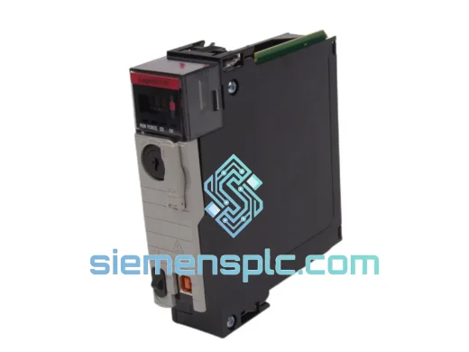
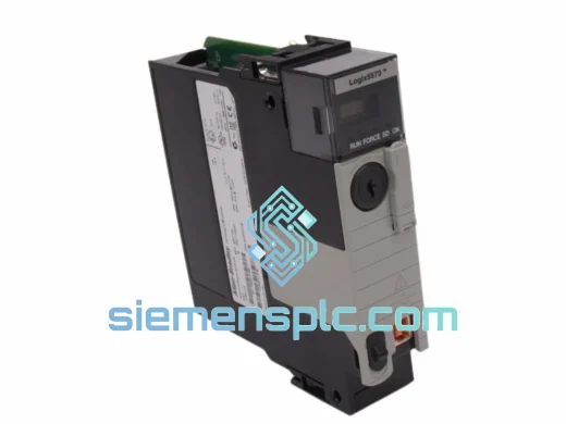
Allen-Bradley 1756-L73 PLC Processor Module – ControlLogix Logix5573
ControlLogix
Origin US
PLC Processor Module
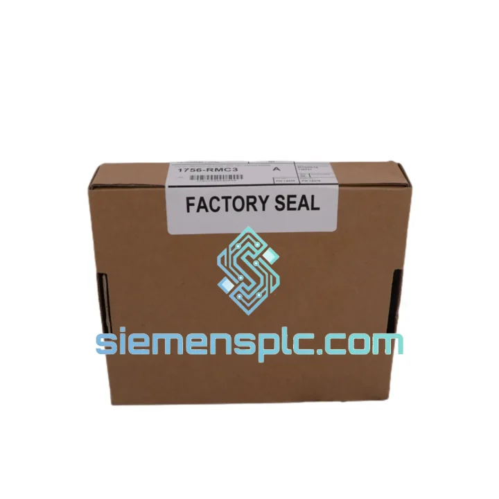
Request verified availability, condition, replacement risk review, packing options and courier lead time for 1756-RMC3.
Click Request Quote and the part number is inserted into the inquiry form automatically.
Core fields for model confirmation and RFQ routing. Detailed product narrative remains below.
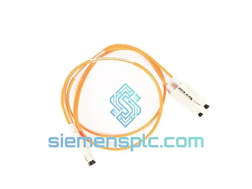
The 1756-RMC3 is a 3-meter duplex multimode fiber optic cable manufactured by Rockwell Automation for exclusive use with the ControlLogix 1756-RM2 Redundancy Module pair. Its singular function is to carry the high-speed chassis synchronization protocol between the primary and secondary ControlLogix chassis, enabling the 1756-RM2 modules to maintain a continuously mirrored controller state. Without this physical link, the RM2 modules cannot arbitrate primary/secondary roles, cannot transfer program state, and cannot execute a bumpless switchover. The cable is therefore not a peripheral accessory — it is the deterministic data path on which the entire hot-standby architecture depends.
In process industries where an unplanned controller outage carries a cost measured in tens of thousands of dollars per hour — power generation, oil and gas processing, water treatment, pharmaceutical batch manufacturing — the 1756-RMC3 is the component that converts a dual-chassis hardware investment into a functioning redundancy system. Its fiber optic medium provides inherent immunity to the electromagnetic interference generated by variable-frequency drives, resistance welding equipment, and arc furnaces that routinely corrupt copper synchronization links in industrial environments.
The LC duplex connectors at both ends are keyed to prevent incorrect insertion. The 3-meter length is dimensioned for the standard spacing between adjacent ControlLogix chassis racks within the same enclosure or across adjacent panels. Rockwell Automation also offers the 1756-RMC1 (1m) for same-rack installations and the 1756-RMC10 (10m) for inter-room configurations.
📦 Real-time Stock & RFQ: [email protected] | WhatsApp: +86 18359268345
| Catalog Number | 1756-RMC3 |
| Manufacturer | Allen-Bradley / Rockwell Automation |
| Series | ControlLogix 1756 RM Series |
| Cable Type | Duplex Multimode Fiber Optic |
| Cable Length | 3 meters (9.84 ft) |
| Connector Type | LC Duplex, both ends (keyed, tool-free field connection) |
| Compatible Modules | 1756-RM2, 1756-RM2/A |
| Fiber Mode | Multimode (sufficient for intra-panel 3m distances) |
| Operating Temperature | 0°C to 60°C (32°F to 140°F) |
| Storage Temperature | -40°C to 85°C |
| Relative Humidity | 5% to 95% non-condensing |
| Approximate Weight | 150 g |
| Redundancy Switchover Time | <10ms (bumpless transfer, chassis-state synchronized) |
| SIL Capability | SIL 2 capable when configured per Rockwell 1756-RM001 Safety Reference Manual |
| Certifications | CE (EMC Directive 2014/30/EU), UL Listed / cUL (UL 508), RoHS (2011/65/EU), IEC 61131-2 |
| Country of Origin | United States |
| Warranty | 12 months from date of shipment |
The 1756-RM2 redundancy module pair operates a continuous cross-chassis arbitration protocol. At any given moment, the active (primary) RM2 transmits a time-stamped state snapshot — encompassing controller tag data, I/O image table, and program scan state — across the fiber link to the standby (secondary) RM2. The secondary module ingests this data stream and maintains a shadow image of the primary controller state, updated on every program scan cycle.
The fiber optic medium is selected for this link for three hardware-level reasons. First, photonic transmission is not subject to electromagnetic induction — the cable carries no electrical potential and therefore cannot act as an antenna for the broadband EMI generated by VFDs (typically 2kHz–20kHz switching frequency), resistance welders (1kHz–100kHz), or arc furnaces. Copper synchronization cables in these environments accumulate induced noise that the RM2 receiver interprets as bit errors, triggering false redundancy fault diagnostics or, in severe cases, spurious switchover events. The 1756-RMC3 eliminates this failure mode at the physical layer.
Second, the fiber medium provides galvanic isolation between the two chassis. In facilities with multiple earthing systems — common in large industrial plants where primary and secondary chassis may be bonded to different structural steel sections — ground potential differences of several volts can exist between cabinet frames. On a copper link, this potential difference drives a common-mode current through the cable shield that corrupts differential signal integrity. Fiber carries no ground reference and is immune to this mechanism.
Third, the LC duplex connector format used on the 1756-RMC3 provides a mechanically positive, keyed connection with a latch retention mechanism. The connector cannot be inserted in the wrong orientation, and the latch prevents accidental disconnection from panel vibration — a relevant consideration in compressor stations and rotating machinery environments where panel vibration amplitudes can reach 2–5g.
The 3-meter cable length is not arbitrary. Rockwell Automation’s ControlLogix redundancy system design guidelines specify that the two chassis forming a redundancy pair should be installed in adjacent rack positions within the same enclosure or in immediately adjacent panels. The 3-meter length provides sufficient reach for this standard layout while minimizing excess cable that would require management within the panel. The multimode fiber specification is appropriate for this distance — single-mode fiber, which offers lower attenuation over longer distances, provides no performance advantage at 3 meters and would add unnecessary cost.
Every 1756-RMC3 unit shipped from our Xiamen, China facility undergoes a structured four-stage inspection before dispatch. Physical authenticity verification confirms label markings, catalog number format, and cable jacket specifications against Rockwell Automation published documentation. LC duplex connector end-faces are inspected under fiber optic microscope per IEC 61300-3-35 cleanliness criteria — contaminated end-faces are the primary cause of optical insertion loss in field installations. Both fiber strands are tested for optical continuity using a visible light source. Packaging integrity and date code documentation are recorded and included with each shipment.
All units are sourced through documented supply channels with chain-of-custody records. Certificate of Conformance is available for each shipment. Export documentation — commercial invoice, packing list, certificate of origin, and HS code classification — is prepared for all international orders as standard practice.
International shipments depart Xiamen via DHL Express, FedEx International Priority, and UPS Worldwide Expedited. Transit times to major industrial hubs: North America 3–5 business days, Europe 4–6 business days, Southeast Asia 2–3 business days, Middle East and Australia 5–7 business days. Same-day dispatch is available for in-stock orders confirmed before 14:00 CST. All shipments are fully insured and tracked from dispatch to delivery confirmation.
📧 Email: [email protected]
📱 WhatsApp: +86 18359268345
🌐 Web: siemensplc.com
📍 Location: Xiamen, China
© 2026 siemensplc.com. All rights reserved.
We check the full part number, brand, series and visible nameplate information before quotation.
Sales confirms stock path, condition option, quantity and realistic lead time for export dispatch.
DHL, FedEx, UPS or buyer courier arrangements can be reviewed with packing requirements.
Similar brand or category products for fast comparison and multi-item RFQ lists.