Allen-Bradley
In Stock OK
Allen-Bradley 1762-L40BWAR Programmable Logic Controller – MicroLogix 1200
Request verified availability, condition, replacement risk review, packing options and courier lead time for 1762-L40BWAR.
BrandAllen-Bradley
Part Number1762-L40BWAR
ConditionAvailability Check
Lead TimeRFQ Confirmation
DocumentsDatasheet / photos by RFQ
ShippingExport packing available
Auto-filled RFQ
1762-L40BWAR
Click Request Quote and the part number is inserted into the inquiry form automatically.
- Reply by email: [email protected]
- WhatsApp / Tel: +86 18359268345
- Mon-Sat 9:00-18:00 GMT+8
Procurement Data
Key Product Information
Core fields for model confirmation and RFQ routing. Detailed product narrative remains below.
- Brand
- Allen-Bradley
- Primary Part Number
- 1762-L40BWAR
- Product Type
- Programmable Logic Controller
- Series / Family
- MicroLogix
- Country of Origin
- US
- Catalog Category
- I/O Modules
- Operating Temp.
- 0°C to +60°C
- Warranty
- 12 months from date of shipment
Model confirmed for inquiry
1762-L40BWAR
Send quantity, destination and urgency. The RFQ form keeps this part number attached.
Request Quote
Product Overview
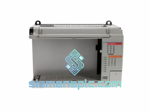
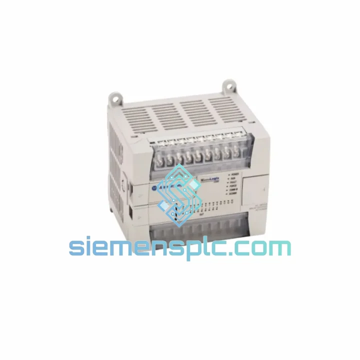
Allen-Bradley 1762-L40BWAR: 40-Point MicroLogix 1200 Controller in Mid-Scale Discrete Automation
The Allen-Bradley 1762-L40BWAR is a fixed-I/O programmable logic controller within Rockwell Automation’s MicroLogix 1200 product family. It integrates 24 DC sink/source digital inputs and 16 Form-A relay outputs into a single DIN-rail-mounted housing, powered by a 120/240V AC supply. The unit carries catalog suffix “R”, denoting the current production hardware revision with updated firmware baseline and revised internal component specifications relative to the earlier 1762-L40BWA.
In a typical discrete control loop — motor sequencing, conveyor interlocking, batch-fill logic — the 1762-L40BWAR functions as the sole decision-making node. It reads field-level sensor states through its 24V DC input bank, executes ladder-logic scan cycles in the range of 0.9 ms per 1K of Boolean instructions, and drives output coils that switch relay contacts rated at 2A resistive per point. The relay output architecture is significant: it allows direct switching of both AC and DC loads without interposing relays, reducing panel component count and associated wiring fault probability.
Real-time clock (RTC) hardware is embedded on the CPU board, enabling time-stamped event logging, shift-differential control logic, and scheduled output activation without auxiliary timer modules. The 8K-word user program memory and 8K-word data file space are sufficient for the majority of standalone machine control applications in the 20–200 I/O point range when combined with up to six 1762-series expansion modules.
📩 Real-time Stock & RFQ: [email protected] | WhatsApp: +86 18359268345
Technical Parameters
| Parameter | Specification |
|---|---|
| Catalog Number | 1762-L40BWAR |
| Hardware Revision | Series R (current production) |
| Total Onboard I/O | 40 points |
| Digital Inputs | 24 × 24V DC, Sink/Source (IEC Type 1/3) |
| Digital Outputs | 16 × Relay, Form A (SPST-NO), 2A @ 240V AC / 30V DC |
| Power Supply Input | 85–265V AC, 47–63 Hz (universal range) |
| Power Consumption | 35W max (base unit, no expansion) |
| User Program Memory | 8K words (ladder logic) |
| Data File Memory | 8K words |
| Scan Time (Boolean) | ~0.9 ms / 1K instructions |
| Communication Port 0 | RS-232, DH-485, DF1 Full/Half Duplex, ASCII |
| Communication Port 1 | RS-232 / RS-485, Modbus RTU Master/Slave, ASCII |
| Expansion Modules | Up to 6 × 1762-series modules |
| Real-Time Clock | Built-in, battery-backed (CR2032) |
| Operating Temperature | 0°C to +60°C |
| Storage Temperature | -40°C to +85°C |
| Relative Humidity | 5–95% non-condensing |
| Enclosure Rating | IP20 / NEMA Type 1 |
| Mounting | 35mm DIN rail or panel mount |
| Dimensions (W×H×D) | Approx. 220 × 90 × 87 mm |
| Weight | Approx. 1.0 kg |
| Certifications | UL 508, CE (EN 61131-2), CSA C22.2 No. 142, cULus |
| Programming Software | RSLogix 500 / RSLogix Micro (v8.0+) |
| Warranty | 12 months from date of shipment |
Hardware Logical Analysis
Input Subsystem — Optical Isolation Architecture: Each of the 24 DC input channels passes through a dedicated optocoupler stage rated at 5mA nominal input current at 24V DC. The optical barrier provides galvanic isolation between field wiring and the CPU backplane bus, with a minimum isolation voltage of 500V AC. Input filter time constants are software-configurable per channel group (0.5 ms to 2 ms), allowing the engineer to trade off noise rejection against response speed depending on sensor type — proximity switches typically run at 1 ms, while encoder feedback may require 0.5 ms.
Output Relay Contact Architecture: The 16 relay outputs use electromechanical Form-A contacts with a rated mechanical life of 10 million operations and an electrical life of 100,000 operations at rated load. Contact material is silver-cadmium oxide (AgCdO), selected for its low contact resistance under inductive load switching — a critical property when driving motor starter coils or solenoid valves where inrush current can reach 6–10× steady-state. Each output group shares a common terminal, allowing mixed-voltage load wiring within a group without additional isolation hardware.
Backplane Communication Bus: The 1762-L40BWAR uses Rockwell’s proprietary 1762 expansion bus, a synchronous serial interface operating at a fixed clock rate that delivers deterministic I/O update timing to expansion modules. The bus master (CPU) polls each expansion module sequentially within the I/O scan, with total expansion bus latency adding approximately 0.5–1.5 ms per module to the overall scan cycle. This architecture guarantees that I/O data presented to the ladder logic program reflects a consistent snapshot — no partial-update race conditions occur between input read and output write phases.
EMC Design: The unit meets EN 61000-4-2 (ESD, ±4kV contact / ±8kV air), EN 61000-4-4 (EFT/Burst, 2kV on power lines), and EN 61000-4-5 (Surge, 1kV line-to-line / 2kV line-to-earth). Internal filtering on the AC power input includes a common-mode choke and X/Y capacitor network, suppressing conducted emissions and providing immunity to power-line transients common in industrial environments with variable-frequency drives or large motor switching loads on the same distribution panel.
Memory Architecture: Program and data memory are stored in battery-backed SRAM, with a lithium coin cell (CR2032) providing retention for up to 5 years under typical conditions. On power loss, the RTC continues to track elapsed time, and the last-known output states are preserved in the data file for use in restart logic. The processor executes a continuous scan cycle: input image update → program execution → output image update → housekeeping (communications servicing, RTC update, diagnostics). Communications are serviced asynchronously via interrupt-driven UART handlers, ensuring that serial traffic on either port does not introduce jitter into the deterministic scan cycle.
System Integration Benefits
- Direct AC/DC Load Switching Without Interposing Relays: The 2A relay contacts handle 240V AC motor starter coils and 24V DC solenoids on the same output bank, eliminating the cost and panel space of external relay modules in mixed-voltage applications.
- Dual-Port Serial Flexibility: Port 0 (RS-232) handles HMI or SCADA connectivity via DF1 protocol; Port 1 (RS-232/485) runs Modbus RTU to third-party instruments — both ports operate concurrently without CPU overhead penalty, enabling simultaneous operator interface and field device communication.
- Deterministic Scan Cycle for Time-Critical Interlocks: With Boolean scan rates below 1 ms/K, the controller resolves safety-relevant interlocks — E-stop chains, guard door monitoring, pressure relief logic — within a single scan cycle, maintaining response times well within IEC 60204-1 requirements for non-safety-rated control.
- Modular Expansion Without Rewiring: Adding a 1762-IF4 analog input module or 1762-OW8 relay expansion requires only DIN-rail mounting and bus connector engagement — no additional power supply or communication wiring. The CPU auto-detects expansion modules at power-up and maps them into the I/O image table.
- RSLogix 500 Ecosystem Compatibility: The 1762-L40BWAR shares its programming environment with the MicroLogix 1000, 1100, 1400, and SLC 500 families. Maintenance engineers familiar with any of these platforms can read, modify, and upload programs without retraining, reducing mean-time-to-repair (MTTR) during unplanned downtime events.
- Built-In Diagnostics Transparency: The CPU continuously monitors its own power supply voltage, memory integrity (checksum), and communication port status. Fault codes are written to the S2 (Status) file and can be read by any connected HMI or SCADA system, providing maintenance personnel with root-cause data without requiring a laptop connection.
- RTC-Driven Scheduled Operations: Time-of-day and calendar-based logic — shift changeover sequences, scheduled lubrication cycles, off-peak energy management — execute without external timers or PLC-to-SCADA time synchronization, reducing system complexity and single-point-of-failure risk.
- EtherNet/IP Upgrade Path: The 1761-NET-ENI module connects to Port 0 and bridges the controller onto an EtherNet/IP network, enabling integration with FactoryTalk View SE, RSLinx Classic, or third-party OPC-UA servers without replacing the controller — protecting the existing capital investment while enabling Industry 4.0 data collection.
Quality Assurance & Global Logistics
Every 1762-L40BWAR unit supplied by siemensplc.com is sourced as genuine Allen-Bradley / Rockwell Automation product. Pre-shipment verification includes catalog number and date code cross-check against Rockwell factory labeling standards, visual inspection of PCB conformal coating and connector integrity, and a functional power-on test confirming LED status indicators and communication port response.
Units are packed in anti-static polyethylene bags, placed in foam-lined corrugated cartons rated for international air freight handling (ISTA 2A standard drop and vibration profiles). Export documentation — commercial invoice, packing list, certificate of origin — is prepared in compliance with Chinese customs regulations and destination-country import requirements.
Shipments originate from our warehouse in Xiamen, China. Standard international delivery timelines: DHL Express 3–5 business days to Europe and North America; FedEx International Priority 2–4 business days to Southeast Asia and the Middle East; EMS/China Post available for cost-sensitive shipments with 7–15 business day transit. Tracking numbers are issued within 24 hours of dispatch. For urgent plant-down situations, same-day dispatch is available for orders confirmed before 14:00 CST.
All units carry a 12-month warranty from the date of shipment, covering manufacturing defects and functional failures under normal operating conditions. Warranty claims are processed with a replacement-first policy to minimize customer downtime.
Contact Information
Email: [email protected]
WhatsApp: +86 18359268345
Web: siemensplc.com
Location: Xiamen, China
© 2026 siemensplc.com. All rights reserved.
Ready to quote
[email protected]
Send This Part Number to Sales
RFQ workflow
Quality workflow ->
Confirmation Process
01Model confirmation
We check the full part number, brand, series and visible nameplate information before quotation.
02Availability reply
Sales confirms stock path, condition option, quantity and realistic lead time for export dispatch.
03Packing & courier
DHL, FedEx, UPS or buyer courier arrangements can be reviewed with packing requirements.
Continue sourcing
Browse full catalog ->
Related Automation Parts
Similar brand or category products for fast comparison and multi-item RFQ lists.

Allen-Bradley
RFQ Ready
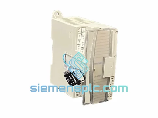
Allen-Bradley 1762-OA8 PLC Output Module – MicroLogix 1762 Series
MicroLogix
Origin US
PLC Output Module
Allen-Bradley
RFQ Ready
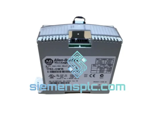
Allen-Bradley 1762-OW16 Relay Output Module
MicroLogix
Origin US
PLC Relay Output Module