Mitsubishi Electric
RFQ Ready
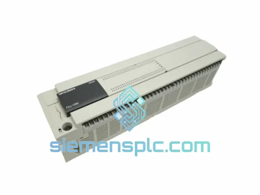
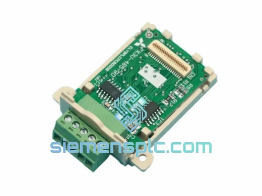
Mitsubishi FX3U-485-BD Communication Board – FX3U Series
MELSEC FX
Origin JP
Communication Board
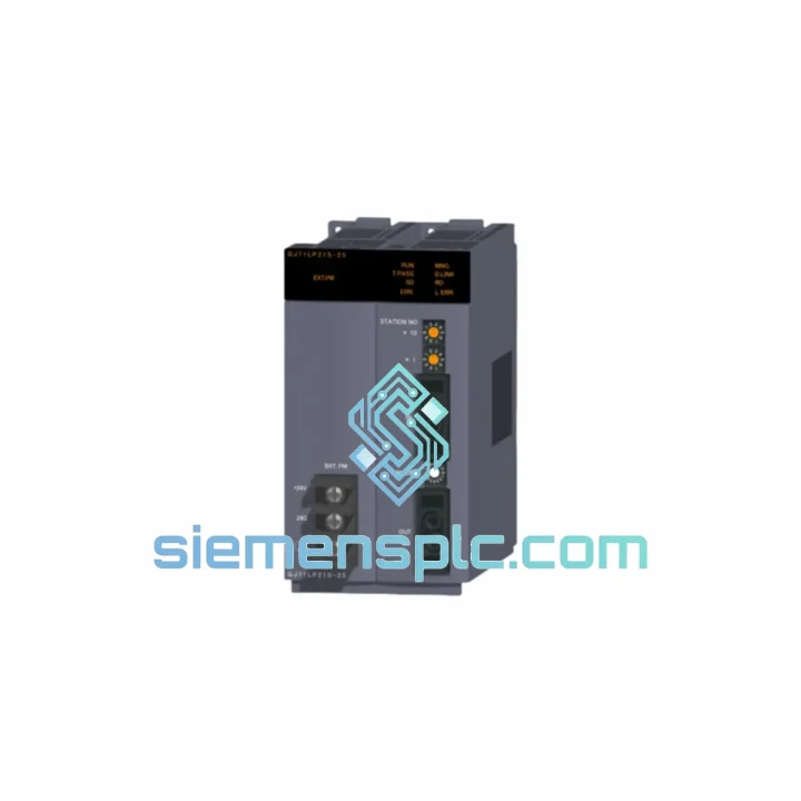
Request verified availability, condition, replacement risk review, packing options and courier lead time for QJ71LP21S-25.
Click Request Quote and the part number is inserted into the inquiry form automatically.
Core fields for model confirmation and RFQ routing. Detailed product narrative remains below.
The QJ71LP21S-25 is a slot-mounted MELSECNET/H network interface module engineered for the Mitsubishi Electric MELSEC-Q Series PLC platform. Operating at a fixed 25 Mbps over SI (Step-Index) plastic optical fiber, it functions as either the cyclic-data control station or a synchronized normal station within ring or bus topologies accommodating up to 64 nodes. Its architectural role in a control loop is unambiguous: by absorbing all token-passing arbitration and LB/LW cyclic refresh operations within its own dedicated network ASIC, the module releases the host Q Series CPU from any network-management overhead, preserving deterministic scan-cycle execution regardless of network load or station count.
This separation of concerns — network processing on the module, application logic on the CPU — is the defining characteristic that makes the QJ71LP21S-25 suitable for synchronized multi-axis motion coordination, safety interlock chains, and process-critical distributed I/O architectures where CPU scan jitter must remain bounded and predictable.
The SI plastic optical fiber medium provides complete galvanic isolation between every node on the ring. Ground-loop currents, common-mode transients, and conducted EMI from adjacent variable-frequency drives, high-voltage switchgear, or arc-welding equipment have no electrical path into the data stream. This is not a software mitigation — it is a physical property of the photonic link, and it eliminates an entire category of field commissioning problems that copper-based fieldbus installations routinely encounter.
📩 Real-time Stock & RFQ: [email protected] | WhatsApp: +86 18359268345
| Parameter | Specification |
|---|---|
| Part Number | QJ71LP21S-25 |
| Manufacturer | Mitsubishi Electric (三菱電機) |
| Compatible Platform | MELSEC-Q Series — Q02H, Q06H, Q12H, Q25H, Q25PRH, QnPH and above |
| Network Protocol | MELSECNET/H |
| Transmission Speed | 25 Mbps (fixed, non-negotiable) |
| Transmission Medium | SI (Step-Index) Plastic Optical Fiber |
| Optical Connector | ST type — dedicated IN port + OUT port |
| Supported Topology | Optical loop (ring) / Optical bus |
| Station Role | Control Station or Normal Station (GX Works2/3 parameter-selectable) |
| Max. Stations per Network | 64 stations |
| Link Bit Devices (LB) | 16,384 points |
| Link Word Devices (LW) | 8,192 points |
| Worst-case Network Cycle Time | < 3.5 ms @ 64 stations, full LB/LW allocation |
| Backplane Bus Current Draw | 0.55 A @ 5 VDC |
| Operating Temperature | 0 °C to +55 °C |
| Storage Temperature | −25 °C to +75 °C |
| Relative Humidity | 5 % to 95 % RH, non-condensing |
| Vibration Resistance | IEC 61131-2 compliant |
| Max. Inter-node Fiber Distance | 30 m (standard SI) / up to 500 m (high-grade SI) |
| Configuration Software | GX Works2 (v1.40S and later) / GX Works3 |
| Module Weight | Approx. 0.34 kg |
| Country of Origin | Japan |
| Warranty | 12 months from confirmed shipment date |
Token-Passing MAC Architecture: The QJ71LP21S-25 implements a deterministic token-passing Media Access Control layer over the MELSECNET/H physical layer. The designated control station holds the token and distributes it sequentially to each normal station. Each station’s network ASIC writes received LB/LW data into a dual-port RAM buffer that is simultaneously accessible by the host CPU’s Q backplane bus. This dual-port architecture decouples network cycle time from CPU scan time: a slow or temporarily unresponsive station does not stall the token ring — it is skipped after a configurable timeout, and the control station logs the absence in the diagnostic BFM area without halting cyclic refresh for the remaining nodes.
Optical Transceiver Front-End: The receive path uses a PIN photodiode with a transimpedance amplifier (TIA) topology, providing a receiver sensitivity of approximately −21 dBm. The LED transmitter output is regulated by a closed-loop automatic power control (APC) circuit that compensates for the temperature-dependent emission efficiency of the plastic LED die across the 0–55 °C operating range. This regulation ensures consistent optical link margin throughout the product’s service life as fiber connectors age and accumulate insertion loss. Because the signal path is entirely photonic between transmitter and receiver, the module inherently satisfies IEC 61000-4-4 (EFT/Burst) and IEC 61000-4-5 (Surge) immunity requirements without supplementary filtering components on the PCB.
Hardware Loop-Back Failover: In ring topology, the module’s network ASIC continuously monitors optical signal presence on the primary receive port. When signal loss persists beyond one token-passing interval — typically under 1 ms — the ASIC asserts a hardware loop-back command. Both the upstream and downstream modules adjacent to the break point fold the ring, restoring a continuous optical path that bypasses the fault. Communication resumes within one network scan cycle. The host CPU receives a diagnostic flag via BFM word 0 but executes no recovery ladder logic; the entire failover sequence is managed in silicon.
Backplane DMA Engine: The module occupies one slot on any Q Series main or extension base and communicates with the CPU via the Q bus at 100 Mbps. An internal DMA engine transfers refreshed LB/LW data directly into the CPU’s device memory area without CPU intervention. The resulting CPU scan overhead for network refresh is below 0.1 ms regardless of the number of link points configured — a figure that remains constant whether 100 or 16,384 LB points are active.
Transient Communication Processor: Separate from the cyclic refresh path, a dedicated message-handling processor manages peer-to-peer READ/WRITE transient requests between any two stations on the network. This processor queues up to 16 concurrent transient requests and arbitrates them independently of the cyclic token cycle. On-demand data operations — recipe downloads, fault log retrieval, parameter writes — are therefore isolated from the deterministic cyclic refresh and cannot introduce jitter into time-critical control data exchange.
Every QJ71LP21S-25 unit dispatched from our Xiamen, China facility is sourced from Mitsubishi Electric’s authorized distribution network or verified industrial surplus channels with full traceability documentation. Each unit passes a structured pre-dispatch inspection before leaving our warehouse:
Standard export logistics from Xiamen: DHL Express and FedEx International Priority with typical transit times of 3–5 business days to Europe, North America, and Southeast Asia. Sea freight LCL/FCL available for bulk orders. All shipments include commercial invoice, packing list, certificate of conformance, and pre-shipment test report. CNAS-accredited third-party inspection available on request. HS Code: 8537.10. Export compliance documentation handled in-house by our logistics team.
📧 Email: [email protected]
💬 WhatsApp: +86 18359268345
🌐 Web: siemensplc.com
📍 Location: Xiamen, China
© 2026 siemensplc.com. All rights reserved.
We check the full part number, brand, series and visible nameplate information before quotation.
Sales confirms stock path, condition option, quantity and realistic lead time for export dispatch.
DHL, FedEx, UPS or buyer courier arrangements can be reviewed with packing requirements.
Similar brand or category products for fast comparison and multi-item RFQ lists.