Bently Nevada
RFQ Ready
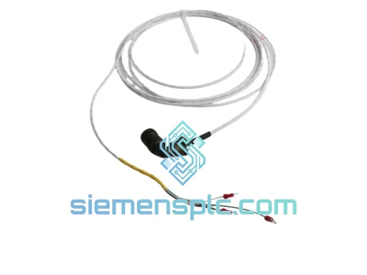
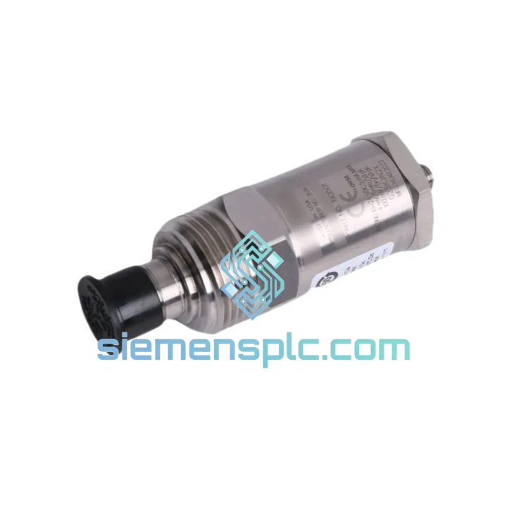
Bently Nevada 991-25-70-01-01 Proximity Probe Extension Cable – 3300 XL Series
3300 XL
Origin US
Proximity Probe Extension Cable
Request verified availability, condition, replacement risk review, packing options and courier lead time for 190501-12-99-00.
Click Request Quote and the part number is inserted into the inquiry form automatically.
Core fields for model confirmation and RFQ routing. Detailed product narrative remains below.
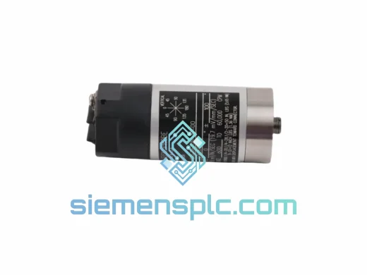
Every hour a critical rotating machine sits idle costs money — sometimes tens of thousands of dollars per hour in lost production, emergency labor, and cascading process disruptions. When a Velomitor CT transducer fails on a compressor train, a steam turbine, or a high-speed pump, the clock starts immediately. The question is not whether you need a replacement — it is how fast you can get one on-site, verified, and back in service. At siemensplc.com, the Bently Nevada 190501-12-99-00 is stocked and ready to ship from Xiamen within hours of order confirmation, not days. Our logistics infrastructure is built around one priority: getting your machine back online before the next production window closes.
The 190501-12-99-00 is a piezoelectric velocity transducer from Bently Nevada’s Velomitor CT family — a series that has become the de facto standard for casing vibration measurement on API 670-compliant machinery protection systems worldwide. Unlike traditional geophone-type sensors with moving coil assemblies that wear out over time, the Velomitor CT uses solid-state piezoelectric technology with integrated IEPE signal conditioning. There are no mechanical parts to fatigue, no coil springs to lose calibration, and no resonance peaks to manage in the operating frequency band. The result is a sensor that delivers consistent, repeatable velocity output across its full service life — right up until the moment it doesn’t, usually due to connector damage, cable failure, or moisture ingress at the mounting interface rather than internal component degradation.
Understanding where these sensors actually fail in the field is what separates a fast, clean replacement from a repeat callout two weeks later. The sections below are written from the perspective of engineers who have handled these exact scenarios — not from a product brochure.
URGENT REQUIREMENT? Contact: [email protected] | WhatsApp: +86 18359268345
| Part Number | 190501-12-99-00 ✅ Ready to Ship |
| Series | Velomitor CT (Continuous Temperature) |
| Manufacturer | Bently Nevada (Baker Hughes) |
| Sensor Technology | Piezoelectric IEPE with integrated signal conditioner |
| Output Type | Velocity-proportional voltage, low-impedance |
| Sensitivity | 100 mV/in/s (3.94 mV/mm/s) nominal |
| Frequency Range | 2 Hz – 2,500 Hz (±3 dB) |
| Measurement Range | 0 – 50 in/s pk (0 – 1,270 mm/s pk) |
| Supply Voltage | 18 – 30 VDC (2-wire current loop compatible) |
| Operating Temperature | -40°C to +121°C (CT-rated for continuous high-temp service) |
| Housing Material | 316 Stainless Steel |
| Connector | 2-pin MIL-C-5015 style |
| Mounting Thread | 1/4-28 UNF stud mount |
| IP Rating | IP67 |
| Weight | Approx. 380 g |
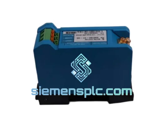
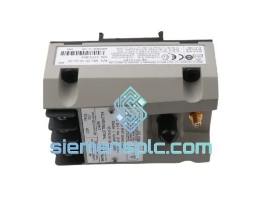
| Compatible Monitors | Bently Nevada 3500/42M, 3500/45, System 1 |
| Compliance | API 670 (5th Ed.), ISO 10816 / ISO 20816 |
| Lead Time | In-stock units ship within 24 hours of order confirmation. For project quantities or urgent shutdown requirements, contact us directly for a committed delivery schedule. |
Most Common Failure Modes in the Field
Before pulling the sensor, rule out the signal chain. A significant percentage of “failed sensor” callouts turn out to be connector corrosion, cable damage at the conduit entry point, or a monitor channel that has drifted out of its bias voltage window. Check these first:
Replacement Procedure — Key Steps
Common Fault Codes on 3500/42M After Sensor Replacement
The Velomitor CT design philosophy starts from the assumption that the sensor will spend its entire service life in an environment that is actively trying to destroy it. Turbomachinery bearing housings run hot — sustained surface temperatures of 80–100°C are common on gas turbine auxiliary equipment, and the CT designation confirms this sensor is rated for continuous operation up to 121°C without performance degradation or accelerated aging of the internal piezoelectric stack.
Vibration immunity is equally critical. The sensor itself is mounted on a machine that may be generating 20–30 g of broadband vibration at the casing surface. The Velomitor CT’s internal construction uses a constrained-layer damping approach that prevents the sensor housing from developing its own resonance within the measurement frequency band — a failure mode that plagues lower-cost sensors and produces false alarm events that erode operator confidence in the monitoring system.
The 316 stainless steel housing and IP67 sealing rating address the moisture and chemical exposure challenge directly. In offshore and coastal installations, salt-laden air attacks sensor housings within months. In petrochemical plants, process fluid mist and steam cleaning cycles create a corrosive environment that destroys standard aluminum-bodied sensors. The 316 SS construction of the 190501-12-99-00 resists chloride-induced pitting corrosion and maintains its dimensional integrity through repeated thermal cycling — ensuring the mounting interface remains leak-free and the connector sealing remains effective throughout the sensor’s service life.
siemensplc.com operates from Xiamen, China — one of the most strategically positioned export hubs in Asia for industrial components. Xiamen Gaoqi International Airport handles daily direct cargo flights to major logistics hubs in Europe, the Middle East, Southeast Asia, and North America, enabling transit times that are genuinely competitive with regional distributors in many markets.
Our standard export process for urgent orders: order confirmation triggers same-day packaging and customs documentation preparation. Export declaration is filed through Xiamen Customs with full HS code compliance (HS 9031.80 for precision measurement instruments). Commercial invoice, packing list, and certificate of origin are prepared in parallel — not sequentially — to eliminate the documentation delays that cause missed flight cutoffs.
Carrier selection is matched to destination and urgency. DHL Express Time Definite is the default for most destinations, with typical transit times of 2–4 business days to Europe and the Middle East, 3–5 days to North America, and 1–2 days to Southeast Asia. FedEx International Priority is available as an alternative where DHL coverage is limited. For extremely time-critical shipments, we can arrange airport-to-airport cargo with local customs broker coordination at the destination — contact us to discuss if your situation requires it.
All shipments include full tracking from pickup to delivery, and our team monitors shipment status proactively. If a customs hold or carrier delay occurs, we notify you immediately and engage our freight forwarder to resolve it — you are not left to chase the carrier yourself during a plant shutdown.
For stock confirmation, urgent quotations, or technical pre-sales support on the Bently Nevada 190501-12-99-00:
© 2026 siemensplc.com. All rights reserved.
We check the full part number, brand, series and visible nameplate information before quotation.
Sales confirms stock path, condition option, quantity and realistic lead time for export dispatch.
DHL, FedEx, UPS or buyer courier arrangements can be reviewed with packing requirements.
Similar brand or category products for fast comparison and multi-item RFQ lists.