GE Fanuc
RFQ Ready
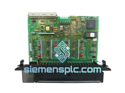
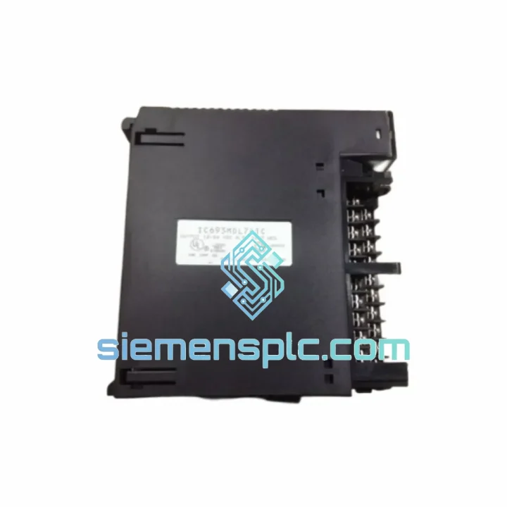
GE Fanuc IC697BEM711 Bus Receiver Module – Series 90-70
Fanuc
Origin US
Bus Receiver Module
Request verified availability, condition, replacement risk review, packing options and courier lead time for IC693MDL741C.
Click Request Quote and the part number is inserted into the inquiry form automatically.
Core fields for model confirmation and RFQ routing. Detailed product narrative remains below.
The IC693MDL741C is a 32-channel, 24 VDC sourcing (PNP) discrete output module designed for the GE Fanuc Series 90-30 programmable controller platform. It occupies a single I/O slot on any standard IC693 baseplate and presents 32 independently switched transistor output points to the field wiring layer. Each channel is rated at 0.5 A continuous at 60 °C ambient, with a module-level aggregate ceiling of 4.0 A when all 32 channels are simultaneously energized. The hardware revision C designation reflects GE Fanuc’s third-generation refinement of the MDL741 output stage, incorporating revised transistor gate drive circuitry and tightened thermal derating curves relative to the A and B revisions documented in GFK-0356.
In the Series 90-30 control loop, the IC693MDL741C occupies the final deterministic switching layer between the CPU’s output image register and the 24 VDC field device network. During each PLC scan cycle, the CPU writes a 32-bit output image word to the module’s onboard dual-port RAM. The module’s local logic latches this image and drives the corresponding transistor output stages within a single backplane bus cycle. Field-side output transition time from CPU write completion to terminal voltage change is bounded below 1 ms under rated resistive and inductive load conditions. This deterministic switching characteristic is a prerequisite for discrete control sequences where output jitter directly affects process timing — sequential valve actuation in batch reactors, coordinated relay switching in motor control centers, or step-indexed tooling sequences in assembly automation.
The module’s optical isolation architecture assigns one dedicated optocoupler per output channel, establishing a 1,500 VAC minimum isolation barrier between the 5 VDC backplane logic domain and the 24 VDC field power domain at every individual point. This per-channel topology differs fundamentally from group-isolation designs used in lower-density modules, where a single barrier serves a block of 8 or 16 channels. In the per-channel design, a field-side fault — shorted load, wiring insulation failure, or inductive kickback exceeding the clamp threshold — is electrically contained within that channel’s transistor stage and optocoupler. The remaining 31 channels continue operating without interruption, and no fault current path exists back through a shared isolation barrier into adjacent channel drive circuits or the backplane bus. Isolation capacitance across each optocoupler is specified below 10 pF, which at 1 MHz presents approximately 16 kΩ of impedance — sufficient to attenuate common-mode noise from variable-frequency drive switching transients to levels below the noise margin of the backplane bus receivers.
Field wiring terminates on a removable terminal block (RTB) compatible with the IC693ACC300 36-pin connector. The RTB’s mechanical latch allows pre-wired field connections to remain undisturbed during module extraction and reinsertion. In continuous-process facilities where maintenance windows are constrained to minutes rather than hours, this characteristic eliminates re-termination as a source of post-maintenance faults and reduces the physical swap interval to the time required to release the module latch and seat the replacement unit.
The IC693MDL741C is slot-compatible with the full range of Series 90-30 baseplates: IC693CHS391 (5-slot), IC693CHS392 (10-slot), IC693CHS393 (10-slot with integrated power supply), IC693CHS398 (5-slot expansion), and IC693CHS399 (10-slot expansion). It is addressable by the complete IC693 CPU family from IC693CPU311 through IC693CPU374. Configuration is supported in both GE Proficy Machine Edition Logic Developer PLC and legacy Logicmaster 90-30 environments, preserving compatibility with existing application code in installed-base systems without requiring program modification.
Real-time Stock & RFQ: [email protected] | WhatsApp: +86 18359268345
| Part Number | IC693MDL741C |
| Manufacturer | GE Fanuc Automation / General Electric |
| Platform | Series 90-30 (IC693 family) |
| Module Function | 32-Point Discrete DC Sourcing Output |
| Hardware Revision | C |
| Output Channel Count | 32 points |
| Output Voltage Range | 24 VDC nominal; 19.2–30 VDC operating range |
| Output Current per Channel | 0.5 A continuous at 60 °C ambient |
| Module Aggregate Current | 4.0 A maximum (all 32 channels ON) |
| Output Transistor Type | Sourcing (PNP); load connected between output terminal and 0 VDC common |
| Output Leakage Current (OFF state) | <1 mA per channel |
| Minimum Load Current | No minimum (compatible with high-impedance loads) |
| Isolation Voltage | 1,500 VAC minimum, field-to-logic, per channel |
| Isolation Architecture | Individual optocoupler per output channel |
| Isolation Capacitance | <10 pF per channel (field-to-logic) |
| Backplane Interface | Series 90-30 parallel I/O bus, dual-port RAM handshake |
| Output Switching Latency | <1 ms, CPU write to field terminal transition |
| Backplane Current Draw | 800 mA @ 5 VDC (logic supply from rack power supply) |
| Field Power Supply | User-supplied 24 VDC; external fusing required per output group |
| Terminal Block | Removable Terminal Block (RTB), IC693ACC300 (36-pin) |
| Conductor Size | 18–22 AWG (0.75–1.5 mm²) |
| Operating Temperature | 0 °C to +60 °C |
| Storage Temperature | −40 °C to +85 °C |
| Relative Humidity | 5%–95%, non-condensing |
| Vibration Resistance | IEC 68-2-6: 5–150 Hz, 1 G |
| Shock Resistance | IEC 68-2-27: 15 G, 11 ms half-sine pulse |
| EMC — EFT/Burst Immunity | IEC 61000-4-4: 2 kV on field terminals |
| EMC — Surge Immunity | IEC 61000-4-5: 1 kV line-to-line |
| EMC — ESD Immunity | IEC 61000-4-2: 4 kV contact, 8 kV air discharge |
| Certifications | UL Listed, CE Marked, CSA Certified |
| Module Weight | Approx. 340 g (without RTB) |
| Compatible Baseplates | IC693CHS391/392/393/398/399 |
| Compatible CPUs | IC693CPU311 through IC693CPU374 |
| Warranty | 12 months against manufacturing defects from dispatch date |
Dual-Port RAM Output Image Handshake: The IC693MDL741C communicates with the Series 90-30 CPU via a dual-port RAM architecture embedded in the backplane interface logic. The CPU writes the 32-bit output image word to a shared memory address space; the module’s local controller reads this address at the I/O update phase and drives the transistor output stages accordingly. The dual-port RAM eliminates bus arbitration latency that would otherwise occur if the CPU and module competed for a single-port memory resource. The result is a fixed, bounded update cycle that does not vary with CPU program scan length — output states are refreshed at the I/O update phase regardless of ladder logic complexity, preserving deterministic response even as application programs grow in size.
Revision C Transistor Gate Drive Redesign: The C revision introduced a revised gate drive resistor network for the output transistors. In the A and B revisions, the gate drive impedance was optimized for switching speed at the expense of slightly elevated dV/dt on the output terminal during turn-on. The C revision increases gate drive impedance marginally, reducing the turn-on dV/dt slope. This change lowers the amplitude of capacitively coupled transients injected into adjacent field wiring during simultaneous multi-channel switching events — a measurable benefit in cable trays where output module wiring runs parallel to analog signal cables over distances exceeding 10 meters. The tradeoff is a turn-on time increase of approximately 50 µs, which is negligible relative to the module’s overall <1 ms switching latency specification.
PCB Ground Plane Partitioning and Ferrite Filtering: The module’s four-layer PCB partitions the field-side switching domain from the logic-side control domain using a dedicated ground plane layer as a Faraday shield between the two signal layers. Each optocoupler LED drive line passes through a ferrite bead filter rated for high impedance above 10 MHz. When an inductive field load — solenoid valve coil, relay coil, or contactor coil — is de-energized, the collapsing magnetic field generates a voltage spike that can reach several hundred volts within microseconds. The ferrite beads present high impedance to these high-frequency transients, preventing them from coupling back through the optocoupler into the logic-side drive circuitry. The module’s IEC 61000-4-4 rating of 2 kV on field terminals confirms that this filtering architecture meets Class A industrial EMC requirements without requiring external suppression components on individual field wiring runs — a significant installation cost reduction in high-density output applications.
Thermal Derating Architecture — Revision C Improvement: GE Fanuc’s hardware manual GFK-0356 documents a reduction in junction-to-ambient thermal resistance of approximately 15% in the C revision relative to the B revision, achieved through a redesigned thermal interface between the output transistor die and the module’s aluminum heat spreader. In practical terms, this allows the module to sustain full 32-channel operation at 0.5 A per channel at higher ambient temperatures before thermal derating becomes necessary. In control panel installations where internal ambient temperatures reach 50–55 °C during peak summer operation — particularly in non-air-conditioned enclosures in tropical or desert climates — this thermal margin improvement directly affects the number of channels that can be simultaneously energized without triggering the module’s thermal protection circuit.
All IC693MDL741C units supplied through siemensplc.com are sourced from verified industrial distribution channels with full lot traceability. Each incoming shipment is inspected against GE Fanuc’s published product identification standards: part number labels, hardware revision markings, and date codes are cross-referenced to confirm unit authenticity and revision level. Functional verification — including backplane communication handshake testing and output channel continuity checks across all 32 points — is performed on sampled units from each lot prior to dispatch. Units that do not pass inspection are quarantined and excluded from customer orders.
Storage and handling follow anti-static protocols throughout the warehouse and packing workflow. Modules are individually sealed in ESD-protective polyethylene bags, cushioned with closed-cell foam inserts rated for international air freight drop testing, and packed in double-wall corrugated cartons. Original GE Fanuc packaging is retained where available. Each shipment includes a packing slip with lot reference and inspection record for customer quality documentation.
Logistics operations are based in Xiamen, China, with direct access to DHL Express, FedEx International Priority, UPS Worldwide Express, and TNT freight networks. Standard orders are dispatched within 1–3 business days of payment confirmation. Express shipments to North America, Europe, Southeast Asia, and the Middle East typically clear customs and arrive within 3–7 business days. Complete export documentation accompanies every international shipment: commercial invoice, packing list, certificate of origin, and airway bill. HS code 8537.10 applies for customs classification. A 12-month warranty against manufacturing defects is included from the dispatch date; warranty claims are processed via [email protected] with proof of purchase and a fault description.
Email: [email protected]
WhatsApp: +86 18359268345
Web: siemensplc.com
Location: Xiamen, China
© 2026 siemensplc.com. All rights reserved.
We check the full part number, brand, series and visible nameplate information before quotation.
Sales confirms stock path, condition option, quantity and realistic lead time for export dispatch.
DHL, FedEx, UPS or buyer courier arrangements can be reviewed with packing requirements.
Similar brand or category products for fast comparison and multi-item RFQ lists.