GE Fanuc
RFQ Ready
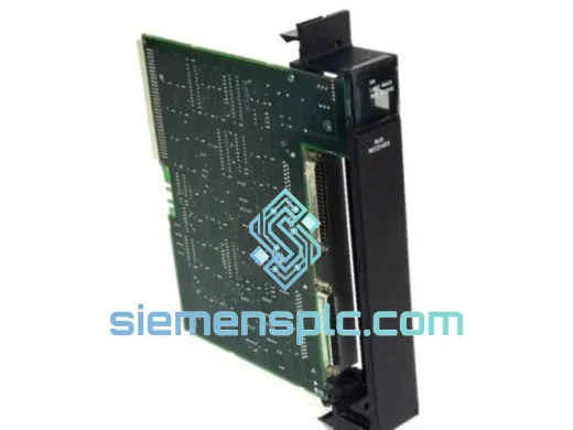
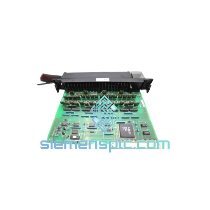
GE Fanuc IC697BEM711 Bus Receiver Module – Series 90-70
Fanuc
Origin US
Bus Receiver Module
Request verified availability, condition, replacement risk review, packing options and courier lead time for IC697MDL970.
Click Request Quote and the part number is inserted into the inquiry form automatically.
Core fields for model confirmation and RFQ routing. Detailed product narrative remains below.
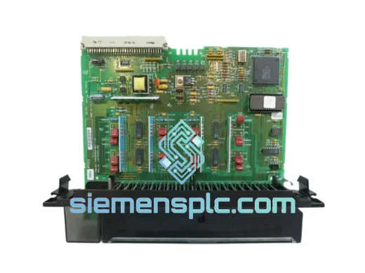
The IC697MDL970 occupies a discrete output slot within the GE Series 90-70 VME-based rack and serves as the final switching element between the PLC’s logic execution layer and field-side actuators. Each of its 16 output channels drives an independent electromechanical relay, making it the preferred choice for applications that demand galvanic isolation, mixed-voltage load switching, and tolerance of inductive transients that would otherwise stress solid-state output stages. In a control loop, this module sits at the command boundary: it receives coil-state data from the CPU over the VME backplane at each scan cycle and translates those binary states into physical contact closures rated for both AC and DC field circuits.
Unlike transistor output modules that share a common emitter rail, the IC697MDL970 relay contacts are fully isolated from one another and from the logic supply. This architecture allows a single module to simultaneously switch 24 VDC solenoids on some channels while controlling 120 VAC motor starters on others — without cross-coupling or ground-loop interference. The optical isolation barrier between the VME logic bus and the relay coil driver circuit provides an additional layer of protection, ensuring that field-side voltage spikes do not propagate back into the CPU’s address/data bus.
Real-time Stock & RFQ: [email protected] | WhatsApp: +86 18359268345
| Parameter | Specification |
|---|---|
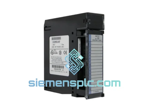
| Part Number | IC697MDL970 |
| Manufacturer | GE Fanuc Automation (GE Intelligent Platforms) |
| Platform | Series 90-70 VME PLC |
| Module Category | Discrete Output — Electromechanical Relay |
| Output Points | 16 relay output channels |
| Output Voltage Range | 5–125 VDC / 5–240 VAC |
| Continuous Output Current | 2 A per point (resistive load) |
| Surge Current Capacity | 10 A for ≤ 10 ms (inrush tolerance) |
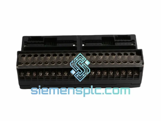
| Isolation Method | Optical isolation (logic-to-field); relay contact isolation (channel-to-channel) |
| Backplane Interface | VME 6U bus — Series 90-70 rack compatible |
| Operating Temperature | 0 °C to +60 °C |
| Storage Temperature | −40 °C to +85 °C |
| Relative Humidity | 5–95 % non-condensing |
| Power Consumption (logic side) | ≤ 3.5 W from backplane 5 VDC rail |
| Module Weight | Approx. 300 g |
| Certifications | CE (LVD + EMC), UL Listed |
| Warranty | 12 months from invoice date |
VME Backplane Data Transfer and Scan Synchronization
The IC697MDL970 maps its 16 output coil states into a single 16-bit output image register that the Series 90-70 CPU writes during the output update phase of each PLC scan. The VME bus arbitration logic on the module accepts a single 16-bit word write transaction, latches all relay coil states simultaneously, and drives the coil driver array in parallel. This parallel-latch architecture eliminates the sequential update skew that would occur if each relay were addressed individually, ensuring that all 16 contacts switch within the same scan boundary — a property critical for coordinated multi-axis sequencing.
Opto-Isolation Barrier Design
Between the VME logic domain (5 VDC, referenced to backplane ground) and the relay coil driver circuit, the module inserts a high-speed optocoupler array. Each optocoupler provides a minimum 1,500 V RMS isolation rating, blocking common-mode transients generated by inductive field loads — motor contactors, solenoid valves, and relay coils — from reaching the backplane data lines. The optocoupler propagation delay is specified at ≤ 1 ms, which is negligible relative to the PLC scan cycle and does not introduce measurable output latency.
Relay Contact Architecture and Inductive Load Handling
Each output channel uses a Form A (SPST-NO) relay contact. The relay coil is driven by a dedicated transistor stage that receives its enable signal from the optocoupler output. A flyback suppression diode across each relay coil clamps the inductive kick generated when the coil de-energizes, protecting the driver transistor from avalanche breakdown. For field-side inductive loads, the module’s contact rating accounts for the L/R time constant of typical industrial actuators; however, external RC snubbers or MOV suppressors are recommended for loads with high inductive energy (e.g., large motor starters above 5 A).
EMC Design Considerations
The module’s PCB layout separates the VME logic section from the relay coil driver section using a ground-plane split, reducing capacitive coupling of high-frequency switching noise from the relay coil drivers back into the backplane signal lines. The relay coil driver traces are routed away from the VME address/data bus traces, and the module’s front panel provides a chassis ground connection point for field cable shields, establishing a low-impedance return path for shield currents that bypasses the logic ground plane.
Every IC697MDL970 unit dispatched from our Xiamen, China facility is a genuine GE Fanuc original component. Prior to shipment, each module undergoes a structured inspection sequence: physical label and housing verification against GE factory markings, connector pin integrity check, and powered functional test in a Series 90-70 compatible test rack confirming relay switching response and backplane communication. Units that do not pass all test criteria are quarantined and not offered for sale.
A 12-month warranty applies from the invoice date. Any unit exhibiting functional failure within the warranty period will be replaced or credited — no deductible, no restocking fee. For project procurement requiring multiple units, batch test reports and certificates of conformance are available upon request.
Logistics from Xiamen are handled via DHL Express, FedEx International Priority, and UPS Worldwide Expedited, with typical transit times of 3–5 business days to Europe, North America, and Southeast Asia. For volume orders, consolidated sea freight and air freight options are available with full export documentation: commercial invoice, packing list, and HS code 8537.10 classification for customs clearance. We serve customers across Asia-Pacific, the Middle East, Europe, North America, South America, and Africa.
📧 Email: [email protected]
📱 WhatsApp: +86 18359268345
🌐 Web: siemensplc.com
📍 Location: Xiamen, China
© 2026 siemensplc.com. All rights reserved.
We check the full part number, brand, series and visible nameplate information before quotation.
Sales confirms stock path, condition option, quantity and realistic lead time for export dispatch.
DHL, FedEx, UPS or buyer courier arrangements can be reviewed with packing requirements.
Similar brand or category products for fast comparison and multi-item RFQ lists.