GE Fanuc
RFQ Ready
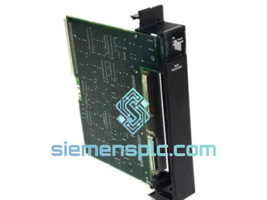
GE Fanuc IC697BEM711 Bus Receiver Module – Series 90-70
Fanuc
Origin US
Bus Receiver Module
Request verified availability, condition, replacement risk review, packing options and courier lead time for IC693ALG391.
Click Request Quote and the part number is inserted into the inquiry form automatically.
Core fields for model confirmation and RFQ routing. Detailed product narrative remains below.
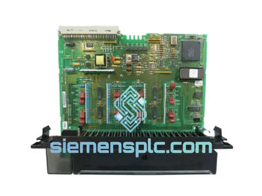
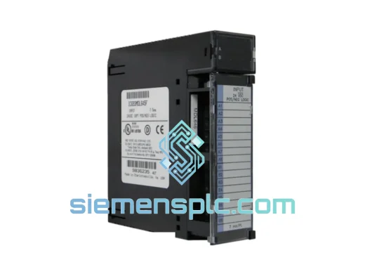
Your Series 90-30 rack just threw a fault. The IC693ALG391 is dead. Your line is stopped, your shift supervisor is breathing down your neck, and the OEM lead time is six weeks. That’s the scenario we built this operation to solve. We stock the GE IC693ALG391 mixed analog I/O module in Xiamen, verified functional, boxed, and ready to clear customs before your maintenance window closes. One call, one shipment, line back up.
URGENT REQUIREMENT? Contact: [email protected] | WhatsApp: +86 18359268345
| Parameter | Specification | Status |
|---|---|---|
| Part Number | IC693ALG391 | ✔ Ready to Ship |
| Manufacturer | GE Fanuc Automation | 100% Original OEM |
| Platform | Series 90-30 PLC | Drop-in Replacement |
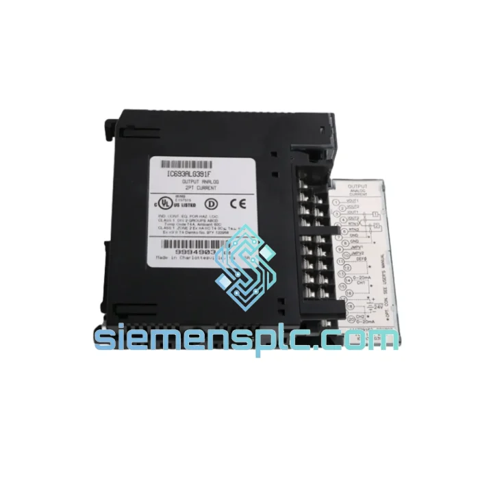
| Module Type | Mixed Analog I/O | — |
| Analog Inputs | 4 channels (4–20 mA / 0–10 V / ±10 V) | Jumper-selectable per channel |
| Analog Outputs | 2 channels (4–20 mA / 0–10 V) | Jumper-selectable per channel |
| Resolution | 12-bit (4096 counts) | — |
| Accuracy | ±0.1% full scale (typical) | — |
| Isolation | Field-to-backplane optical isolation | — |
| Operating Temp | 0°C to +60°C | — |
| Storage Temp | -40°C to +85°C | — |
| Humidity | 5%–95% non-condensing | — |
| Backplane Power | 5 VDC via backplane bus | — |
| Certifications | UL Listed, CE Marked | — |
| Compatible CPUs | IC693CPU311/313/321/331/340/341/350/360/363/364/374 | All Series 90-30 CPUs |
| Compatible Chassis | IC693CHS391/392/393/398/399 | 5-slot & 10-slot |
| Ship From | Xiamen, China | ✔ Same-Day Dispatch Available |
Common fault signatures that point to a failed IC693ALG391:
Step-by-step hot-swap replacement procedure (Series 90-30 with redundant power):
Configuration items to verify post-replacement:
The IC693ALG391 was engineered for continuous 24/7 operation in environments that would kill consumer-grade electronics inside a week. The optical isolation barrier between field terminals and the backplane logic bus is not a marketing checkbox — it is the module’s primary defense against the ground loops, common-mode noise, and inductive transients that are endemic to motor-heavy industrial floors. In practice, this means a 480 VAC drive fault that induces a 200 V transient on a 4–20 mA loop will blow a fuse or trip a barrier, not take out your CPU.
Thermal design accommodates the full 0–60°C operating range without derating. Conformal coating on the PCB resists condensation ingress in applications where ambient humidity swings between shifts — common in food processing, coastal chemical plants, and unheated outdoor enclosures in subtropical climates. Vibration tolerance meets IEC 68-2-6 test profiles, making the module suitable for installation on skid-mounted equipment and mobile platforms where chassis flex is a real concern.
Units in our inventory are stored in climate-controlled conditions, individually bagged in anti-static packaging, and inspected for physical damage and connector integrity before dispatch. We do not ship modules with bent backplane connector pins, corroded terminals, or cracked housings — the three physical defects most commonly found in grey-market surplus stock.
Our dispatch hub is in Xiamen, Fujian — one of China’s primary export ports with direct DHL and FedEx gateway access. Here is what the logistics chain looks like from your purchase order to your receiving dock:
Email: [email protected]
WhatsApp: +86 18359268345
Web: siemensplc.com
© 2026 siemensplc.com. All rights reserved.
We check the full part number, brand, series and visible nameplate information before quotation.
Sales confirms stock path, condition option, quantity and realistic lead time for export dispatch.
DHL, FedEx, UPS or buyer courier arrangements can be reviewed with packing requirements.
Similar brand or category products for fast comparison and multi-item RFQ lists.