Siemens
RFQ Ready
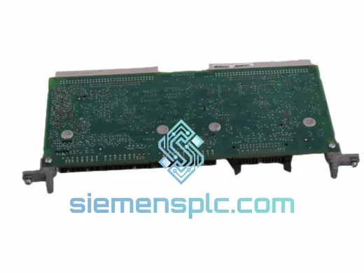
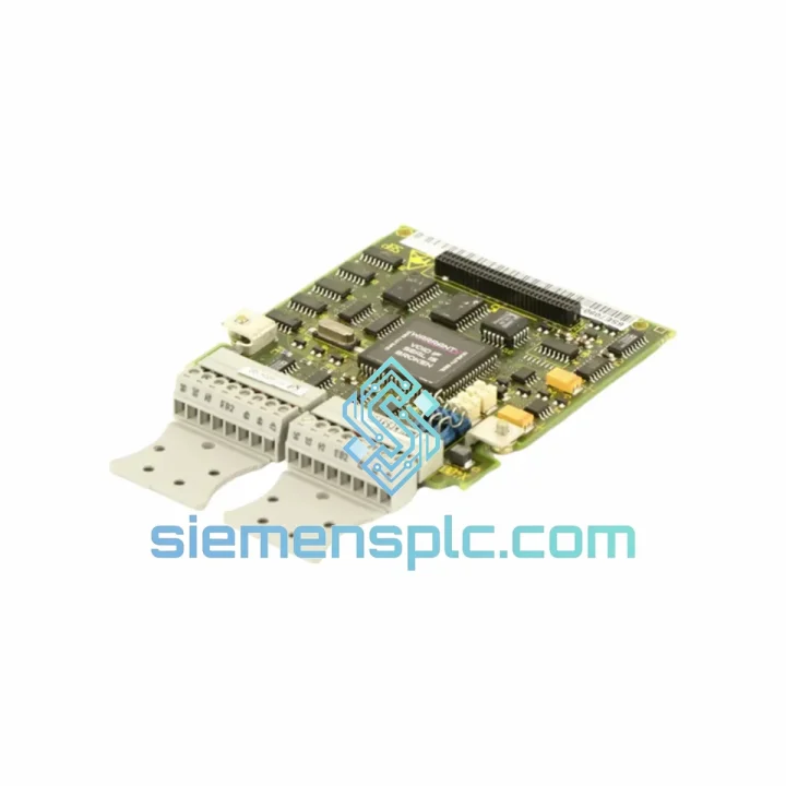
Siemens 6SY7000-0AA78 ES300-9655 Drive I/O Board
MASTERDRIVES
Origin DE
Drive I/O Board
Request verified availability, condition, replacement risk review, packing options and courier lead time for 6SX7010-0KC00.
Click Request Quote and the part number is inserted into the inquiry form automatically.
Core fields for model confirmation and RFQ routing. Detailed product narrative remains below.
The 6SX7010-0KC00 is a terminal extension board manufactured by Siemens AG for the MASTERDRIVES variable-speed drive platform. Its function within a drive control system is structurally distinct from passive wiring accessories: it serves as the physical and electrical boundary between field-level instrumentation wiring and the drive’s internal Control Unit (CU) signal processing chain. In industrial installations where a single drive axis must simultaneously accept an analog speed reference from a supervisory PLC, digital enable/inhibit commands from a safety relay, and encoder feedback from a motor-mounted transducer, the 6SX7010-0KC00 provides the organized, electrically conditioned termination interface that makes this signal convergence reliable and maintainable.
The board mounts directly within the MASTERDRIVES enclosure chassis, positioning it at the shortest possible electrical distance from the CU’s analog-to-digital conversion front-end and digital optocoupler input stage. This proximity is not incidental — it is a deliberate design constraint. Every additional meter of unshielded conductor between a field signal source and the drive’s A/D converter introduces a proportional increase in susceptibility to conducted interference from the drive’s own PWM output stage, which operates at switching frequencies between 2 kHz and 16 kHz depending on the configured pulse pattern. By terminating field signals at the board and routing them internally to the CU via controlled-impedance PCB traces, the 6SX7010-0KC00 keeps the analog signal path inside the EMC-shielded enclosure rather than exposed to the panel wiring environment.
Analog input channels on the board support ±10 V voltage signals and 0–20 mA / 4–20 mA current loop inputs, covering the full range of PLC analog output card formats in common use across Siemens S7, Allen-Bradley ControlLogix, and Schneider Modicon platforms. The differential input stage provides a common-mode rejection ratio (CMRR) adequate to suppress ground potential differences of up to ±7 V between the signal source and the drive’s analog reference ground — a specification that becomes operationally significant in large panel assemblies where cable runs between cabinet sections exceed 10 meters and ground potential differences are measurable. Input impedance is matched to the MASTERDRIVES CU’s A/D front-end to prevent source loading from introducing gain error into the speed or torque reference signal.
Digital I/O channels accept 24 V DC logic signals in both PNP (sourcing) and NPN (sinking) configurations, accommodating the full range of PLC digital output card types without external signal conversion. Each digital input channel is protected by a transient voltage suppressor (TVS) diode network rated to clamp inductive switching transients — generated by contactors, solenoid valves, and relay coils sharing the same 24 V DC supply rail — to within the optocoupler’s absolute maximum input voltage rating. The optocouplers provide a minimum 2,500 V RMS galvanic isolation barrier between field wiring and the CU’s internal logic ground, conforming to IEC 61800-3 Category C2 EMC requirements for variable-speed drives in industrial environments.
The PCB construction is multi-layer FR4 with controlled impedance on signal routing layers, a dedicated ground pour separating the analog signal plane from the digital logic plane, and conformal coating applied to the component side for resistance to moisture ingress and airborne contamination in environments classified up to IEC 60721-3-3 Class 3C2. Terminal contact surfaces are gold-plated to prevent oxidation-induced contact resistance drift over the board’s service life in humid or chemically active atmospheres. Screw-type terminals are compatible with cage-clamp tooling for high-density wiring operations.
Real-time Stock & RFQ: [email protected] | WhatsApp: +86 18359268345
| Parameter | Specification |
|---|---|
| Part Number | 6SX7010-0KC00 |
| Manufacturer | Siemens AG |
| Product Series | SIEMENS MASTERDRIVES |
| Component Type | Terminal Extension Board |
| Compatible Platforms | MASTERDRIVES MC, VC, FC series |
| Terminal Type | Screw-type, cage-clamp compatible |
| Analog Input Range | ±10 V DC; 0–20 mA; 4–20 mA |
| Digital I/O Logic Level | 24 V DC, PNP and NPN compatible |
| Galvanic Isolation (Digital) | ≥2,500 V RMS via optocoupler |
| EMC Compliance | IEC 61800-3 Category C2 |
| Operating Temperature | 0 °C to +55 °C |
| Storage Temperature | −25 °C to +70 °C |
| Relative Humidity | 5% to 95% RH, non-condensing |
| PCB Construction | Multi-layer FR4, conformal coated |
| Mounting Interface | Direct chassis mount, MASTERDRIVES enclosure |
| Country of Origin | Germany |
| Unit Weight | 740 g |
| Warranty | 12 months from shipment date |
The 6SX7010-0KC00 implements a passive-active hybrid signal conditioning architecture. On the analog side, the differential input stage is the first active element in the signal chain: it rejects common-mode noise before the signal reaches the A/D converter, which means that interference coupled onto both conductors of a twisted-pair field cable — the dominant noise coupling mechanism in drive panels — is attenuated at the input stage rather than digitized and propagated into the speed reference calculation. The CMRR of the differential stage is specified to remain effective across the frequency range of conducted interference generated by the drive’s own IGBT switching events, which produce harmonic content extending into the low MHz range.
The PCB layout enforces a hard separation between the analog signal plane and the digital switching plane through a dedicated ground pour that acts as a Faraday shield between the two domains. This layout discipline suppresses capacitive coupling of digital switching transients — generated by the optocoupler drive circuits and the CU’s microprocessor clock — into the analog signal traces. In drive environments where the analog speed reference resolution is 12 bits or higher, a single coupled transient of sufficient amplitude can produce a velocity step in the closed-loop speed controller that is indistinguishable from a legitimate reference change, causing torque disturbances in tension-sensitive or positioning applications.
The TVS diode protection network on each digital input channel is sized to handle the energy content of inductive switching transients from 24 V DC relay coils and solenoid valves with coil inductances up to several hundred millihenries — the range typical of industrial control panel components sharing the same supply rail as the drive’s digital I/O. The clamping response time of the TVS network is in the sub-nanosecond range, ensuring that the transient is suppressed before it can forward-bias the optocoupler’s input LED beyond its absolute maximum rating.
Gold-plated terminal contacts maintain stable contact resistance over the board’s service life in environments where copper oxidation or sulfide film formation would otherwise increase contact resistance to levels that affect signal integrity on low-current analog circuits. The conformal coating on the component side provides a physical barrier against condensation and particulate contamination without impeding heat dissipation from the board’s low-power active components.
Each 6SX7010-0KC00 unit supplied through siemensplc.com is a genuine Siemens AG manufactured component. Part authenticity is verified by cross-referencing OEM part markings, PCB silkscreen revision codes, and factory date code stamps against Siemens reference documentation. Units with any discrepancy in marking, component population, or construction quality are excluded from inventory prior to listing.
Pre-shipment inspection covers visual examination under magnification for PCB damage and solder joint integrity, terminal contact condition assessment, dimensional verification of the chassis mounting interface, and continuity testing of terminal-to-backplane connector paths where applicable. Inspection records are retained and provided to customers on request.
Packaging conforms to IEC 61340-5-1 ESD protection requirements: each board is sealed in a static-dissipative bag with a humidity indicator card, placed in a foam-lined rigid carton rated for international air freight handling loads. Outer carton labeling includes part number, batch reference, and fragile/ESD handling instructions.
Dispatch operations are based in Xiamen, China, with direct access to DHL Express, FedEx International Priority, and UPS Worldwide Expedited services. Standard export documentation — commercial invoice, packing list, and certificate of origin — is prepared for all shipments. HS code classification support and customs pre-clearance documentation are available on request. In-stock units are dispatched within 1–2 business days of order confirmation. Indicative air express transit times: 3–5 business days to Europe; 4–6 business days to North America; 2–4 business days to Southeast Asia. All units carry a 12-month warranty from shipment date, covering manufacturing defects and functional failure under normal operating conditions as defined in Siemens MASTERDRIVES product documentation.
Email: [email protected]
WhatsApp: +86 18359268345
Web: siemensplc.com
Location: Xiamen, China
© 2026 siemensplc.com. All rights reserved.
We check the full part number, brand, series and visible nameplate information before quotation.
Sales confirms stock path, condition option, quantity and realistic lead time for export dispatch.
DHL, FedEx, UPS or buyer courier arrangements can be reviewed with packing requirements.
Similar brand or category products for fast comparison and multi-item RFQ lists.