Bently Nevada
RFQ Ready
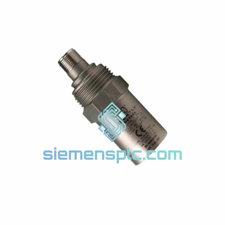
Bently Nevada 991-25-50-01-00 Thrust Transmitter – 3500 Series
3500 Series
Origin US
Thrust Transmitter
Request verified availability, condition, replacement risk review, packing options and courier lead time for 190501-04-00-00.
Click Request Quote and the part number is inserted into the inquiry form automatically.
Core fields for model confirmation and RFQ routing. Detailed product narrative remains below.
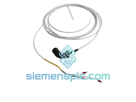
The 190501-04-00-00 is a single-axis, self-generating electromagnetic velocity transducer manufactured by Bently Nevada (a Baker Hughes business). Its function within a rotating machinery protection architecture is to produce a continuous analog voltage signal proportional to the instantaneous absolute velocity of the machine casing at the mounting point. Unlike proximity probes — which measure shaft relative displacement with respect to the bearing housing — this sensor measures the absolute motion of the housing structure itself, providing a measurement channel that is physically and informationally independent from shaft-relative data. In API 670-compliant protection systems, both measurement types are required for complete machinery protection coverage; neither substitutes for the other.
The transduction mechanism is purely electromagnetic and requires no external power supply at the sensor head. An inertial coil assembly — a wound copper coil bonded to a calibrated spring suspension — is positioned concentrically within the static field of a fixed permanent magnet housed in the sensor body. The spring-mass system is tuned to a natural resonant frequency of approximately 7–9 Hz. Below this frequency, the coil tracks the housing motion with negligible relative displacement and produces no meaningful output. Above resonance, the coil’s inertia causes it to remain approximately stationary in space while the housing and magnet assembly move with the machine casing. The resulting relative velocity between coil conductors and magnetic field lines generates an EMF per Faraday’s law: V = BLv, where B is the flux density, L is the effective conductor length, and v is the relative velocity. The output is a low-impedance analog voltage with a nominal sensitivity of 20 mV per mm/s (500 mV per in/s), usable across a flat ±3 dB frequency band from 10 Hz to 1,000 Hz.
The -04 suffix in the part number encodes the connector body style, shell diameter, and pin assignment. This suffix is a mandatory procurement specification parameter. Within the 190501 product family, different suffix variants use physically distinct connector shells with different keying arrangements. Substituting a -01 or -02 variant without verifying mating connector compatibility at the junction box and monitor card field wiring terminal will result in a wiring fault that may not be immediately apparent during loop check if the incorrect connector physically mates but with reversed or misassigned pins. Procurement and spare parts management procedures must treat the full part number — including suffix — as the minimum acceptable specification granularity.
Mounting is via a 1/4-28 UNF or M8 threaded stud into a tapped boss on the bearing cap or machine casing. Stud mounting achieves a mounting interface resonant frequency typically above 5,000 Hz, well above the sensor’s 1,000 Hz upper measurement limit, ensuring the interface introduces no compliance-related attenuation within the measurement band. Adhesive or magnetic mounting methods are not acceptable for permanent protection applications: both introduce interface compliance that attenuates high-frequency signal content and degrades effective upper frequency response, producing a systematic under-reading of high-frequency vibration components.
The 316 stainless steel housing is rated IP67 per IEC 60529, qualifying the sensor for continuous operation in oil mist, water spray, steam condensation, and periodic wash-down environments. The operating temperature range of -40°C to +121°C covers the full installation envelope of most turbomachinery, centrifugal compressor, and steam turbine applications without requiring thermal insulation or heat tracing at the sensor body. The sensor mass of approximately 140 g is low enough that stud-mounted installation does not require supplementary mechanical support in standard bearing housing geometries.
Real-time Stock & RFQ: [email protected] | WhatsApp: +86 18359268345
| Parameter | Specification |
|---|---|
| Manufacturer | Bently Nevada (Baker Hughes) |
| Full Part Number | 190501-04-00-00 |
| Sensor Operating Principle | Passive electromagnetic induction (self-generating) |
| Measurement Axis | Single axis, absolute casing velocity |
| Nominal Sensitivity | 20 mV/(mm/s) [500 mV/(in/s)] ±5% |
| Usable Frequency Range (±3 dB) | 10 Hz – 1,000 Hz |
| Internal Resonant Frequency | ~7–9 Hz (below measurement band) |
| Transverse Sensitivity | <5% of primary axis sensitivity |
| Coil DC Resistance | ~1,500 Ω (at 20°C reference) |
| Recommended Monitor Input Impedance | >100 kΩ (3300/3500 series standard) |
| Supply Power Required | None — self-generating output |
| Output Signal Type | Analog voltage, low impedance |
| Operating Temperature | -40°C to +121°C (-40°F to +250°F) |
| Storage Temperature | -55°C to +150°C |
| Ingress Protection | IP67 per IEC 60529 |
| Housing Material | 316 stainless steel |
| Connector Type | 2-pin MIL-C-5015 style, -04 shell/pin configuration |
| Mounting Thread | 1/4-28 UNF or M8 threaded stud |
| Sensor Mass | ~140 g |
| Compatible Monitor Platforms | Bently Nevada 3300 Series; 3500/42M Velocity Input Module |
| Applicable Standard | API 670 (Machinery Protection Systems) |
| Warranty | 12 months from confirmed shipment date |
Spring-Mass Inertial Coil Dynamics: The coil suspension spring constant k and coil assembly mass m are selected to place the system’s natural frequency fn = (1/2π)√(k/m) at 7–9 Hz. This positions fn below the 10 Hz lower measurement limit, ensuring the sensor operates entirely in the supra-resonant regime during normal machinery monitoring. In this regime, the coil’s inertia dominates over the spring restoring force, and the coil displacement relative to the magnet is proportional to the absolute casing displacement — while the time derivative of this displacement (the coil-to-magnet relative velocity) is proportional to the absolute casing velocity. The output voltage is therefore a direct, linear representation of casing velocity without requiring differentiation or integration in the signal conditioning chain.
Source Impedance and Monitor Input Loading Analysis: The coil’s ~1,500 Ω DC resistance forms a resistive voltage divider with the monitor card’s input impedance Zin. At the 3500/42M’s Zin of >100 kΩ, the signal attenuation factor is 1,500/(1,500 + 100,000) = 1.47%, corresponding to a sensitivity error of less than 0.13 dB — within the sensor’s ±5% sensitivity tolerance and negligible for protection applications. Engineers integrating this sensor with third-party monitors having Zin below 10 kΩ must apply a correction factor to the effective sensitivity: Veffective = Vnominal × Zin/(Zin + 1,500). Failure to apply this correction results in alarm setpoints calibrated against an understated signal amplitude, creating a systematic under-protection condition that will not be detected during standard loop check procedures.
EMC Shielding Architecture: The 316 stainless steel housing provides electrostatic shielding against capacitively coupled interference from adjacent power cables, bus bars, and variable-frequency drive output conductors. The MIL-C-5015 connector shell maintains a continuous metallic ground path for the cable shield, ensuring that shield-induced currents return through the connector body rather than through the signal conductors. In installations within 1 meter of VFD output cables — where common-mode noise can exceed 10 V peak at switching frequencies of 2–16 kHz — this shielding architecture maintains signal-to-noise ratios sufficient for reliable detection of casing velocity amplitudes as low as 0.5 mm/s RMS without supplementary filtering at the monitor input card.
Thermal Resistance Variation and OK Circuit Implications: Copper’s temperature coefficient of resistance (TCR) is approximately 3,930 ppm/°C. Across the full -40°C to +121°C operating range (161°C span), the coil resistance varies by approximately ±31.6% from the 20°C reference value of ~1,500 Ω — a range of approximately 1,025 Ω to 1,975 Ω. The 3500/42M card’s OK circuit monitors coil impedance to detect open-circuit and short-circuit faults. Commissioning engineers must configure the OK circuit’s resistance acceptance window to span this full thermal range; a window set at ambient temperature only will generate false NOT OK alarms when the sensor operates at elevated bearing housing temperatures near the upper end of its rated range.
Connector Suffix Traceability and Procurement Control: The -04 suffix designates a specific MIL-C-5015 shell size, keying index, and pin-to-signal assignment. This configuration mates with a defined cable assembly connector and junction box terminal block. Procurement teams must verify suffix consistency across three items: the sensor (190501-04-00-00), the mating cable assembly, and the monitor card’s field wiring terminal assignment documentation. A mismatch at any of these three points creates a wiring fault that may pass a continuity check but fail a polarity check, resulting in an inverted output signal that causes the monitor to read velocity in the wrong phase — a condition that does not trigger an alarm but corrupts the vibration waveform data used for diagnostic analysis.
All 190501-04-00-00 units supplied through siemensplc.com are sourced via traceable distribution channels with documented batch-level provenance referenced to Baker Hughes manufacturing records. Each unit processed through our Xiamen facility undergoes a structured pre-shipment verification sequence: coil DC resistance measurement against the factory specification window (~1,500 Ω ±10% at 20°C ambient); visual inspection of the housing, connector shell, and cable jacket for mechanical damage or corrosion; thread gauge verification of the 1/4-28 UNF or M8 mounting stud interface; and label authentication against Baker Hughes’ published serial number and date code formats. Units that fail any criterion are quarantined and excluded from shipment without exception.
Original OEM packaging is preserved where intact. Units without original packaging are repackaged in anti-static foam-lined cartons with silica gel desiccant inserts, heat-sealed against moisture ingress during ocean or air freight transit. Export documentation — commercial invoice, packing list, certificate of origin, and HS code declaration — is prepared for every international shipment to facilitate customs clearance in the destination country. Dangerous goods declarations are not required for this product class.
Dispatch from Xiamen is available via DHL Express, FedEx International Priority, and UPS Worldwide Expedited, with typical door-to-door transit times of 3–5 business days to Europe, North America, the Middle East, and Southeast Asia. In-stock units ship within 1–3 business days of payment confirmation. Sea freight consolidation from Xiamen Port is available for bulk orders where transit time is not the primary constraint. A 12-month warranty from the confirmed shipment date covers manufacturing defects under normal operating and installation conditions as defined in the Bently Nevada product documentation.
Email: [email protected]
WhatsApp: +86 18359268345
Web: siemensplc.com
Location: Xiamen, China
© 2026 siemensplc.com. All rights reserved.
We check the full part number, brand, series and visible nameplate information before quotation.
Sales confirms stock path, condition option, quantity and realistic lead time for export dispatch.
DHL, FedEx, UPS or buyer courier arrangements can be reviewed with packing requirements.
Similar brand or category products for fast comparison and multi-item RFQ lists.