ABB
In Stock OK
ABB SDCS-PIN-11 3ADT306100R1 Power Interface Board – DCS 400/500 Series
Request verified availability, condition, replacement risk review, packing options and courier lead time for SDCS-PIN-11.
BrandABB
Part NumberSDCS-PIN-11
ConditionAvailability Check
Lead TimeRFQ Confirmation
DocumentsDatasheet / photos by RFQ
ShippingExport packing available
Auto-filled RFQ
SDCS-PIN-11
Click Request Quote and the part number is inserted into the inquiry form automatically.
- Reply by email: [email protected]
- WhatsApp / Tel: +86 18359268345
- Mon-Sat 9:00-18:00 GMT+8
Procurement Data
Key Product Information
Core fields for model confirmation and RFQ routing. Detailed product narrative remains below.
- Brand
- ABB
- Primary Part Number
- SDCS-PIN-11
- Product Type
- Power Interface Board
- Product Family
- Other series
- Country of Origin
- SE
- Catalog Category
- Industrial Automation Spares
- Warranty
- 12 months against manufacturing defects from date of dispatch
Model confirmed for inquiry
SDCS-PIN-11
Send quantity, destination and urgency. The RFQ form keeps this part number attached.
Request Quote
Product Overview
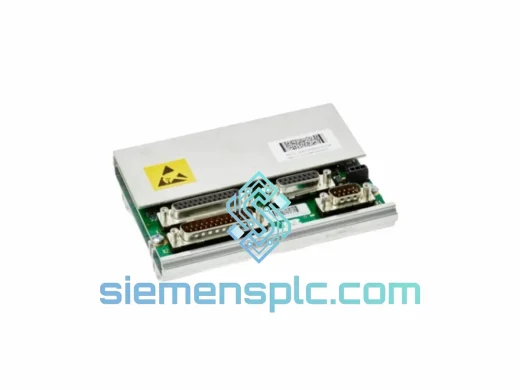
ABB SDCS-PIN-11 (3ADT306100R1) — Power Interface Board for DCS 400/500 DC Drive Systems
The SDCS-PIN-11, catalogued under ABB order code 3ADT306100R1, is the dedicated power interface board (PIN board) within the ABB DCS 400 and DCS 500 family of fully digital DC drive controllers. Its primary function is to condition, isolate, and route the high-voltage feedback signals — armature voltage, field current, and thyristor firing pulses — between the power stack and the SDCS-CON series control board. Without a correctly functioning PIN board, the control loop loses its voltage and current measurement references, making closed-loop speed and torque regulation impossible.
In a DCS 400/500 drive architecture, the control board (SDCS-CON-2 or SDCS-CON-4) handles all digital processing: speed reference generation, PID regulation, and fieldbus communication. The SDCS-PIN-11 acts as the analogue front-end that translates real-world power circuit signals into logic-level inputs the control board can process. It also carries the gate drive circuitry that fires the thyristor bridge at the precise phase angle calculated by the control algorithm. This division of function — digital control isolated from high-voltage power — is the architectural basis for the drive’s EMC compliance and its ability to operate reliably in electrically noisy industrial environments.
Real-time Stock & RFQ: [email protected] | WhatsApp: +86 18359268345
Technical Parameters
| Parameter | Specification |
|---|---|
| Part Number | SDCS-PIN-11 |
| ABB Order Code | 3ADT306100R1 |
| Compatible Drive Series | ABB DCS 400 / DCS 500 |
| Board Function | Power Interface Board — armature voltage sensing, field current feedback, thyristor gate drive |
| Isolation Architecture | Galvanic isolation between power circuit and control logic via opto-coupler and transformer barriers |
| Gate Drive Output | Pulse transformer-coupled firing pulses to thyristor bridge (6-pulse or 12-pulse topology) |
| Armature Voltage Sensing Range | Up to 1000 V DC (drive-frame dependent) |
| Field Current Feedback | Analogue current transducer input, scaled per drive frame |
| Mounting Interface | PCB plug-in module; direct backplane connector to SDCS-CON control board |
| Operating Ambient Temperature | 0 °C to +55 °C (inside drive cabinet) |
| Storage Temperature | −40 °C to +70 °C |
| Relative Humidity | 5–95% RH, non-condensing (IEC 60068-2-78) |
| PCB Weight | Approx. 640 g |
| Compliance | CE (LVD + EMC Directive), RoHS 2011/65/EU |
| Warranty | 12 months against manufacturing defects from date of dispatch |
Hardware Logical Analysis
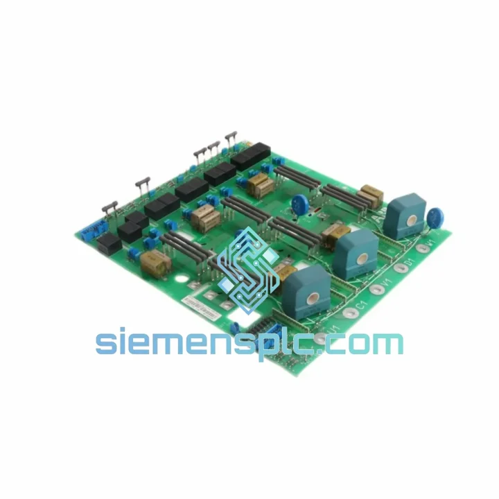
The SDCS-PIN-11 board is structured around three discrete functional blocks, each engineered to address a specific challenge in high-power DC drive interfacing.
1. Galvanic Isolation Barrier
All signal paths crossing from the power circuit side to the control logic side pass through either opto-coupler stages or small-signal pulse transformers. The opto-couplers used in the armature voltage measurement chain provide a minimum isolation voltage consistent with the drive’s rated armature voltage class, preventing any fault-induced voltage transient on the power bus from propagating into the SDCS-CON control board. This is not a passive protection measure — the opto-coupler bandwidth is selected to pass the 50/60 Hz fundamental and its low-order harmonics accurately, which is the signal content the control algorithm uses for voltage regulation.
2. Thyristor Gate Drive Chain
The firing pulse path runs from the SDCS-CON board’s digital output through the SDCS-PIN-11’s pulse transformer array to the thyristor gate-cathode terminals. Pulse transformers are used rather than direct opto-coupler drive because they can deliver the peak gate current (typically 0.5–1.5 A for industrial thyristors) required for reliable turn-on across the full operating temperature range. The transformer-coupled design also ensures that the gate drive circuit floats at the cathode potential of each thyristor, eliminating the need for isolated gate drive power supplies for each device — a significant simplification in a 6-pulse bridge with six thyristors.
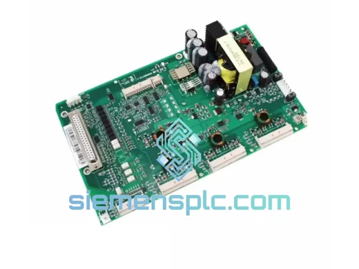
3. EMC Design and Conducted Noise Suppression
The board layout follows a split-ground plane strategy: the high-voltage analogue section and the low-voltage digital section are separated by a physical gap on the PCB, with all cross-boundary signals routed through the isolation components. Decoupling capacitors are placed at each IC power pin, and ferrite beads are used on signal lines entering the isolation boundary. This layout discipline is what allows the DCS 400/500 drive to meet EN 61800-3 Category C2 EMC limits without external filtering on the control wiring.
4. Field Current Measurement Path
The field excitation current feedback is routed through a dedicated analogue input on the SDCS-PIN-11. The signal conditioning chain includes a precision resistor shunt or Hall-effect transducer interface (depending on drive frame), followed by an instrumentation amplifier stage that rejects common-mode noise from the field winding supply. Accurate field current measurement is the prerequisite for field-weakening operation — the control algorithm cannot extend the speed range above base speed without a reliable field current signal.
System Integration Benefits
- Deterministic Control Loop Closure: By providing low-latency, isolated analogue feedback to the SDCS-CON board, the SDCS-PIN-11 enables the drive’s current control loop to execute at its designed sample rate (typically 1–2 ms), maintaining torque response consistency under load transients.
- Direct Plug-In Replacement: The board connects via a defined backplane connector with no mechanical modification to the drive frame. Replacement time in a planned maintenance window is under 30 minutes for a trained technician.
- Fault Isolation Architecture: Because the PIN board is a discrete, replaceable module, a board-level fault (e.g., a failed opto-coupler from a voltage surge) does not require replacement of the entire drive. This reduces repair cost to the component level.
- Compatibility with SDCS-CON-2 and SDCS-CON-4: The SDCS-PIN-11 interfaces with both generations of the DCS 400/500 control board, protecting the investment in existing drive infrastructure when upgrading the control board.
- Support for 6-Pulse and 12-Pulse Bridge Topologies: The gate drive section of the SDCS-PIN-11 is designed to fire a standard 6-pulse thyristor bridge. In 12-pulse configurations, two drive units operate in tandem, each with its own PIN board, providing redundant gate drive paths.
- Diagnostic Transparency: The SDCS-CON board monitors the integrity of the firing pulse feedback signals routed through the SDCS-PIN-11. A missing or distorted pulse triggers a drive fault (F-code) that identifies the specific thyristor arm, enabling targeted maintenance rather than broad troubleshooting.
- Thermal Stability of Measurement Accuracy: The precision resistors and instrumentation amplifiers on the analogue measurement chain are specified for low temperature coefficient (typically <50 ppm/°C), ensuring that armature voltage and field current readings remain within calibration across the full 0–55 °C operating range without field recalibration.
- Reduced MTTR for High-Value Production Lines: Stocking the SDCS-PIN-11 as a critical spare reduces mean time to repair on DC motor drives in continuous-process industries — steel, paper, mining — where each hour of unplanned downtime carries measurable production cost.
Quality Assurance & Global Logistics
Every SDCS-PIN-11 unit dispatched from our Xiamen, China facility is sourced from verified ABB-authorized distribution channels. Prior to dispatch, each board undergoes a structured inspection protocol:
- Part Number Verification: ABB order code 3ADT306100R1 confirmed against the board’s silk-screen marking and label. Any discrepancy results in quarantine and supplier notification.
- Visual and Physical Inspection: PCB surface examined for component integrity, solder joint condition, connector pin alignment, and absence of physical damage or corrosion.
- ESD-Safe Packaging: Boards are packed in anti-static bags with desiccant, placed in foam-lined cartons rated for international air freight handling. Moisture barrier packaging is applied for sea freight shipments.
- Traceability Documentation: Certificate of conformity, sourcing records, and inspection checklist are available upon request — supporting ISO 9001 and IEC 62402 (obsolescence management) documentation requirements for MRO and OEM procurement teams.
- Shipping from Xiamen, China: We dispatch via DHL Express, FedEx International Priority, and UCP air freight. Standard transit times: 3–5 business days to Europe and North America, 2–4 business days to Southeast Asia. Customs documentation (commercial invoice, packing list, HS code declaration) prepared to the destination country’s import requirements.
- 12-Month Warranty: All units carry a 12-month warranty against manufacturing defects from the date of dispatch. Warranty claims are processed with replacement dispatch within 5 business days of confirmed fault diagnosis.
Contact Information
Email: [email protected]
WhatsApp: +86 18359268345
Web: siemensplc.com
Location: Xiamen, China
© 2026 siemensplc.com. All rights reserved.
Ready to quote
[email protected]
Send This Part Number to Sales
RFQ workflow
Quality workflow ->
Confirmation Process
01Model confirmation
We check the full part number, brand, series and visible nameplate information before quotation.
02Availability reply
Sales confirms stock path, condition option, quantity and realistic lead time for export dispatch.
03Packing & courier
DHL, FedEx, UPS or buyer courier arrangements can be reviewed with packing requirements.
Continue sourcing
Browse full catalog ->
Related Automation Parts
Similar brand or category products for fast comparison and multi-item RFQ lists.
ABB
RFQ Ready
ABB 3HAC9330-1 Robot Speed Reducer – IRB6640-205/2.7
lRB240046 RB460
Origin SE
Robot Speed Reducer
ABB
RFQ Ready
ABB YT204001-JJ Speed Measurement Board
Ready to Ship
Origin SE
Speed Measurement Board