ABB
In Stock OK
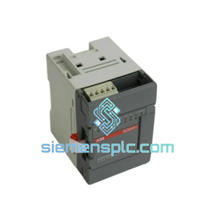
ABB XO08R1 1SBP260101R1001 PLC I/O Module – AC500
Request verified availability, condition, replacement risk review, packing options and courier lead time for XO08R1 XOO8R1-B04 1SBP260101R1001.
BrandABB
Part NumberXO08R1 XOO8R1-B04 1SBP260101R1001
ConditionAvailability Check
Lead TimeRFQ Confirmation
DocumentsDatasheet / photos by RFQ
ShippingExport packing available
Auto-filled RFQ
XO08R1 XOO8R1-B04 1SBP260101R1001
Click Request Quote and the part number is inserted into the inquiry form automatically.
- Reply by email: [email protected]
- WhatsApp / Tel: +86 18359268345
- Mon-Sat 9:00-18:00 GMT+8
Procurement Data
Key Product Information
Core fields for model confirmation and RFQ routing. Detailed product narrative remains below.
- Brand
- ABB
- Primary Part Number
- XO08R1 XOO8R1-B04 1SBP260101R1001
- Product Type
- PLC I/O Module
- Series / Family
- AC500
- Manufacturer
- ABB
- Country of Origin
- SE
- Model Function
- Digital Output Extension Module — Relay Type
- Catalog Category
- Industrial Automation Spares
- Warranty
- 12 months from date of shipment against manufacturing defects
Model confirmed for inquiry
XO08R1 XOO8R1-B04 1SBP260101R1001
Send quantity, destination and urgency. The RFQ form keeps this part number attached.
Request Quote
Product Overview
ABB XO08R1 (1SBP260101R1001): 8-Channel Relay Output Module in the AC500 Distributed I/O Architecture
The XO08R1 occupies a well-defined functional position within the ABB AC500 control loop: it serves as the terminal relay stage between the CPU’s process image output (PIO) and field-side actuators. Every scan cycle, the AC500 CPU resolves its application logic, writes the resulting output byte to the internal expansion bus, and the XO08R1’s relay driver array translates those eight discrete logic states into galvanically isolated dry-contact closures. This architecture decouples the PLC backplane voltage domain entirely from the field circuit, which is the foundational requirement for controlling 24 VDC solenoids, 230 VAC motor contactors, and indicator lamps within the same module without cross-interference.
Unlike transistor output modules that share a common emitter rail and impose polarity constraints on field wiring, the XO08R1’s relay contacts are potential-free. Each channel’s NO contact can switch an independent voltage source — a property that simplifies panel wiring in mixed-voltage installations and eliminates the need for interposing relays in the majority of field device scenarios. The module draws its logic power from the AC500 internal bus, requiring no dedicated 24 VDC auxiliary supply for the relay coil drive circuitry, which reduces BOM complexity in compact panel designs.
📦 Real-time Stock & RFQ: [email protected] | WhatsApp: +86 18359268345
Technical Parameters
| Part Number | XO08R1 |
| ABB Catalog Reference | 1SBP260101R1001 |
| Manufacturer | ABB |
| Platform / Series | AC500 |
| Module Function | Digital Output Extension Module — Relay Type |
| Output Channels | 8 × independent relay outputs (NO contact) |
| Contact Type | Normally Open (NO), potential-free dry contact |
| Rated Switching Voltage | 250 VAC / 30 VDC |
| Max Continuous Current per Channel | 2 A |
| Max Inrush Current | 10 A (≤ 20 ms) |
| Minimum Switching Load | 10 mA at 5 VDC |
| Relay Mechanical Endurance | ≥ 10,000,000 operations |
| Relay Electrical Endurance | ≥ 100,000 operations at rated resistive load |
| Bus Interface | AC500 internal expansion bus (direct plug-in coupling) |
| Logic Power Supply | Via AC500 internal bus — no external auxiliary supply required |
| Operating Temperature Range | −25 °C to +60 °C |
| Storage Temperature Range | −40 °C to +70 °C |
| Relative Humidity | 5–95 % RH, non-condensing |
| Degree of Protection | IP20 (IEC 60529) |
| Mounting | 35 mm DIN rail (EN 60715) |
| Approx. Dimensions (W × H × D) | 45 mm × 100 mm × 75 mm |
| Approx. Weight | 200 g |
| EMC Immunity | IEC 61000-4-2 (ESD), IEC 61000-4-4 (EFT/Burst), IEC 61000-4-5 (Surge) |
| Certifications | CE, UL, cUL (refer to ABB datasheet 2CDC135001D0201 for full listing) |
| Country of Origin | Germany |
| Warranty | 12 months from date of shipment against manufacturing defects |
Hardware Logical Analysis
Relay Driver Stage and Coil Suppression: The XO08R1 uses a dedicated relay driver IC per channel, typically a Darlington transistor array or equivalent gate-drive topology, to energize the relay coil from the internal bus logic voltage. A flyback diode is integrated across each coil to clamp the inductive kickback voltage when the coil is de-energized, protecting the driver IC from transient overvoltage. This is a non-trivial design detail: without proper coil suppression, repeated switching of inductive relay coils generates voltage spikes that can couple into adjacent signal traces and degrade the MTBF of the driver stage over time.
Galvanic Isolation Architecture: The relay contact provides inherent galvanic isolation between the PLC logic domain (typically 3.3 V or 5 V internal bus) and the field circuit (up to 250 VAC). The isolation barrier is the physical air gap and creepage distance of the relay contact assembly, which meets the requirements of IEC 60664-1 for reinforced insulation at 250 VAC. This is structurally superior to optocoupler-based transistor outputs in high-voltage field environments, where leakage current through the optocoupler’s parasitic capacitance can cause nuisance triggering of sensitive field devices.
EMC Design Considerations: The module’s PCB layout routes the relay coil drive lines away from the contact output terminals to minimize capacitive coupling between the switching transient on the coil side and the field circuit. The internal bus interface uses differential signaling with common-mode chokes to reject conducted interference from the field side propagating back into the CPU backplane. The metal DIN-rail clip provides a low-impedance chassis ground path, which, when bonded to the panel earth bar, forms part of the EMC shielding strategy for the overall control cabinet.
Status LED Indication Logic: Each channel has a dedicated LED driven directly from the relay coil drive signal, not from the contact state. This means the LED reflects the commanded output state from the CPU, not the actual contact closure. In fault diagnosis, a discrepancy between LED state and field device response points to a field-side fault (open circuit, blown fuse, failed actuator) rather than a module fault — a diagnostic distinction that reduces mean time to repair (MTTR) in production environments.
System Integration Benefits
- Zero auxiliary power wiring: The XO08R1 draws all logic and coil drive power from the AC500 internal bus. Panel designers eliminate one 24 VDC terminal block row and the associated fusing per module, reducing wiring labor by an estimated 15–20 minutes per module in a typical panel build.
- Mixed-voltage field wiring on a single module: Channels can independently switch 24 VDC, 110 VAC, and 230 VAC field devices without any hardware reconfiguration. This is particularly valuable in retrofit projects where legacy field devices operate at non-standard voltages.
- Deterministic scan-cycle integration: The module’s output update latency is bounded by the AC500 CPU scan cycle time plus the relay operate time (typically 5–10 ms). For non-time-critical discrete outputs such as valve commands and indicator lamps, this latency is well within process requirements and is fully deterministic — a prerequisite for IEC 61511 functional safety assessments of the non-safety portions of the control loop.
- Diagnostic transparency via Automation Builder: ABB’s Automation Builder / PS501 Control Builder Plus software provides per-channel output force and monitor functions. Maintenance engineers can force individual relay outputs from the programming environment during commissioning without modifying the application program, reducing commissioning time for multi-actuator systems.
- Modular scalability without I/O bus reconfiguration: Adding an XO08R1 to an existing AC500 rack requires only physical insertion and address assignment in the hardware configuration. The CPU automatically detects the new module at startup via the internal bus enumeration protocol, eliminating manual DIP switch addressing found in older I/O systems.
- Long-term spare parts availability: The AC500 platform has a documented 10-year product lifecycle commitment from ABB. The XO08R1’s catalog reference (1SBP260101R1001) has remained stable across AC500 V2 and V3 hardware generations, ensuring backward compatibility for spare parts procurement without re-engineering the hardware configuration.
- Reduced panel footprint: At approximately 45 mm wide, the XO08R1 provides 8 relay output channels in a housing narrower than many standalone relay modules. In a 600 mm wide panel, this translates to a measurable reduction in DIN-rail length required for equivalent output channel count.
- Inductive load compatibility with external snubber support: The relay contacts are rated for resistive loads at 2 A. For inductive loads (solenoid valves, contactor coils), the contact arc energy is managed by fitting an RC snubber or metal oxide varistor (MOV) across the load terminals. This is standard practice and does not require any modification to the module itself, preserving warranty validity.
Quality Assurance & Global Logistics
Every ABB XO08R1 unit offered through siemensplc.com is sourced from verified supply channels with full traceability to ABB’s manufacturing and distribution network. Incoming inspection covers label authentication (part number, date code, serial number cross-referenced against ABB’s product identification guidelines), physical condition assessment, and where applicable, a functional power-on verification to confirm relay coil energization and LED response on all eight channels.
ABB’s manufacturing quality system for the AC500 platform is certified to ISO 9001 and the modules are produced in facilities compliant with IEC 61131-2 environmental and electrical requirements. The XO08R1 carries CE marking under the Low Voltage Directive and EMC Directive, with UL/cUL listing for North American markets. Each unit ships with its original ABB packaging and documentation where available, preserving the factory seal integrity that procurement teams in regulated industries (pharmaceutical, oil & gas, nuclear auxiliary systems) require for incoming inspection records.
Logistics operations are based in Xiamen, China — a major export hub with direct access to DHL Express, FedEx International Priority, and UPS Worldwide Express services. Standard export documentation (commercial invoice, packing list, certificate of origin, HS code 8537.10 classification) is prepared for every international shipment. For time-critical requirements, same-day dispatch is available for orders confirmed before 14:00 CST. Typical transit times: 2–4 business days to Europe and North America via express courier. A 12-month warranty against manufacturing defects is provided from the date of shipment, with RMA processing handled directly from Xiamen.
Contact Information
Email: [email protected]
WhatsApp: +86 18359268345
Web: siemensplc.com
Location: Xiamen, China
© 2026 siemensplc.com. All rights reserved.
Ready to quote
[email protected]
Send This Part Number to Sales
RFQ workflow
Quality workflow ->
Confirmation Process
01Model confirmation
We check the full part number, brand, series and visible nameplate information before quotation.
02Availability reply
Sales confirms stock path, condition option, quantity and realistic lead time for export dispatch.
03Packing & courier
DHL, FedEx, UPS or buyer courier arrangements can be reviewed with packing requirements.
Continue sourcing
Browse full catalog ->
Related Automation Parts
Similar brand or category products for fast comparison and multi-item RFQ lists.
ABB
RFQ Ready
ABB GJR2370800R0200 88FN02A-E Bus Coupling Device – S500 I/O
AC500
Origin SE
Bus Coupling Device