Bently Nevada
RFQ Ready
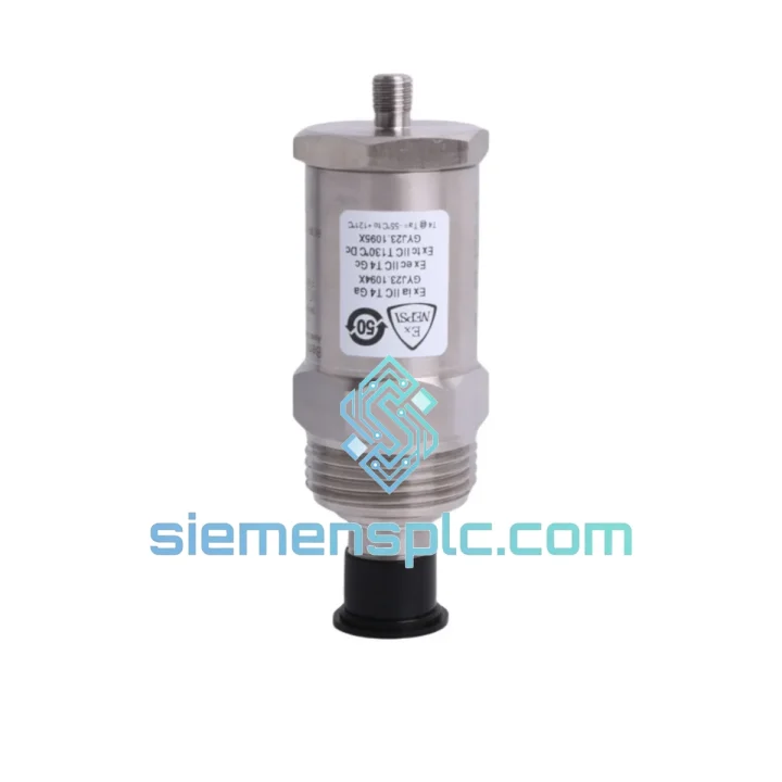
Bently Nevada RS901104-03-050-10-01 Proximitor Sensor – 3300 XL Series
3300 XL
Origin US
Proximitor Sensor
Request verified availability, condition, replacement risk review, packing options and courier lead time for 190501-14-00-04.
Click Request Quote and the part number is inserted into the inquiry form automatically.
Core fields for model confirmation and RFQ routing. Detailed product narrative remains below.
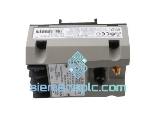
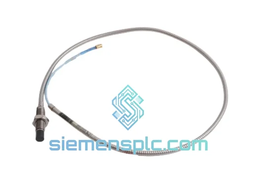
A failed velocity transducer on a critical rotating machine is not a maintenance ticket — it is a production stoppage. When your 3500-series rack throws a Not OK on the velocity channel and the turbine or compressor trips offline, every hour of delay compounds the financial damage. The Bently Nevada 190501-14-00-04 Velomitor CT is a piezo-velocity seismic transducer purpose-built for absolute casing vibration measurement on high-value rotating assets. We stock it in Xiamen, China, and ship globally via DHL and FedEx express — because your plant cannot wait for a six-week OEM lead time.
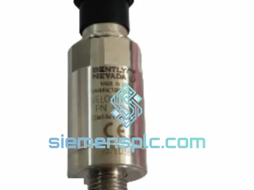
The 190501-14-00-04 is a self-generating, passive piezo-velocity sensor. It requires no external power supply, produces a voltage output directly proportional to casing velocity, and integrates without modification into any Bently Nevada 3500/42M Velocity Monitor slot. Its hermetically sealed stainless steel housing and MIL-spec 2-pin connector make it the standard choice for steam turbines, gas compressors, centrifugal pumps, and large electric motors operating under API 670 machinery protection requirements.
URGENT REQUIREMENT? Contact: [email protected] | WhatsApp: +86 18359268345
| Parameter | Specification |
|---|---|
| Part Number | 190501-14-00-04 |
| Brand | Bently Nevada (Baker Hughes) |
| Series | Velomitor CT |
| Sensor Type | Piezo-velocity (passive, self-generating) |
| Measurement | Absolute casing vibration velocity |
| Output Signal | Voltage proportional to velocity (no external power required) |
| Sensitivity | 100 mV/in/s (3.937 mV/mm/s) |
| Frequency Range | 2 Hz – 1,000 Hz |
| Operating Temperature | -40°C to +121°C (-40°F to +250°F) |
| Housing Material | 316 stainless steel, hermetically sealed |
| Connector | 2-pin MIL-C-5015 style |
| Cable Length (integral) | Per suffix code: -04 = 4-meter armored cable |
| Weight | Approx. 380 g |
| Compliance | API 670, CE, RoHS |
| Warranty | 12 months against manufacturing defects |
| Stock Status | Ready to Ship – Xiamen, China |
Before pulling the transducer, confirm the fault is in the sensor and not the cable or monitor card. The 3500/42M will display a Channel Not OK condition for both an open-circuit transducer and a shorted cable — these are electrically identical from the rack’s perspective. Perform the following checks in sequence to avoid replacing a good sensor:
Step 1 — Isolate the cable. Disconnect the field cable at the junction box. Measure resistance across the transducer’s two pins directly at the sensor body. A healthy 190501-14-00-04 reads approximately 1.5 kΩ to 3 kΩ at ambient temperature. An open circuit (OL) or near-zero reading confirms sensor failure.
Step 2 — Check the cable run. With the sensor disconnected, measure cable continuity from the junction box to the rack terminal. Shield continuity and pin-to-pin isolation should both pass. A shorted cable will mimic a dead sensor on the rack display.
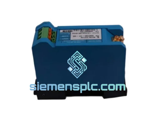
Step 3 — Verify monitor configuration before installing the replacement. The 3500/42M channel must be configured for velocity input (not proximity or acceleration). Confirm the full-scale range and alert/danger setpoints match your machinery protection specification. If the channel was previously configured for a different transducer type, a configuration download via System 1 or the 3500 Rack Configuration Software is required before the new sensor will produce valid readings.
Step 4 — Mounting torque and orientation. The 190501-14-00-04 uses a standard 1/4-28 UNF stud mount. Apply 5–7 N·m torque. Mounting orientation affects low-frequency response — install with the sensing axis perpendicular to the shaft centerline for radial casing measurements, or axially for thrust-direction monitoring per your machinery protection drawing.
Step 5 — Post-installation verification. After installation, perform a static output check: with the machine at rest, the 3500/42M should read near-zero velocity (typically <0.01 in/s RMS). Any elevated static reading indicates a loose mounting surface or residual mechanical vibration from adjacent equipment. Run the machine to minimum governor speed and confirm the channel transitions to OK status and the velocity reading is within the expected baseline band from your historical trend data.
Common fault codes on 3500/42M associated with this transducer:
The Velomitor CT platform was designed for continuous service in environments that destroy standard industrial sensors within months. The 190501-14-00-04 addresses three primary failure mechanisms that account for the majority of field returns on velocity transducers:
Thermal cycling fatigue. Steam turbine casings routinely cycle between ambient and 150°C+ during start-stop sequences. The hermetically sealed 316 stainless steel housing eliminates moisture ingress during cool-down phases — the primary cause of internal piezo element corrosion and sensitivity drift in non-sealed designs. The -40°C to +121°C operating range covers the full thermal envelope of most process plant applications without derating.
High-cycle mechanical fatigue. At 3,000 RPM, a turbine casing experiences 50 vibration cycles per second. Over a 12-month operating period, the sensor accumulates over 1.5 billion mechanical cycles. The Velomitor CT’s internal piezo stack is potted in a vibration-damping compound that decouples the sensing element from the housing resonance, preventing fatigue cracking at the element-to-housing interface — a known failure mode in earlier-generation velocity sensors.
EMI and ground loop immunity. The 2-pin MIL-spec connector and armored cable construction of the -04 suffix variant provide shielded signal transmission that rejects common-mode electrical noise from variable-frequency drives, large motor starters, and high-current bus bars in the immediate vicinity. The passive (no-power) design eliminates the ground loop paths that cause baseline drift in active sensor designs.
Our warehouse is located in Xiamen, China — one of China’s primary export hubs with direct DHL, FedEx, and UPS express lanes to major industrial regions worldwide. For urgent plant maintenance requirements, we operate on the following dispatch schedule:
We accept T/T bank transfer, L/C at sight, and PayPal for international orders. Minimum order quantity is 1 unit. Volume pricing available for project BOM procurement.
Email: [email protected]
WhatsApp: +86 18359268345
Web: siemensplc.com
Location: Xiamen, China
© 2026 siemensplc.com. All rights reserved.
We check the full part number, brand, series and visible nameplate information before quotation.
Sales confirms stock path, condition option, quantity and realistic lead time for export dispatch.
DHL, FedEx, UPS or buyer courier arrangements can be reviewed with packing requirements.
Similar brand or category products for fast comparison and multi-item RFQ lists.