GE Fanuc
RFQ Ready
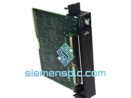
GE Fanuc IC697BEM711 Bus Receiver Module – Series 90-70
Fanuc
Origin US
Bus Receiver Module
Request verified availability, condition, replacement risk review, packing options and courier lead time for IC693MDL730F.
Click Request Quote and the part number is inserted into the inquiry form automatically.
Core fields for model confirmation and RFQ routing. Detailed product narrative remains below.
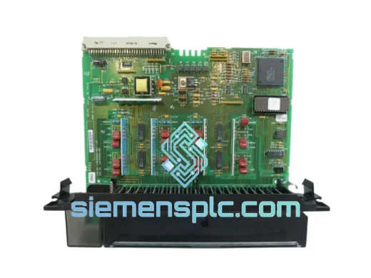
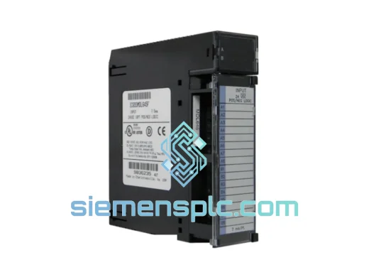
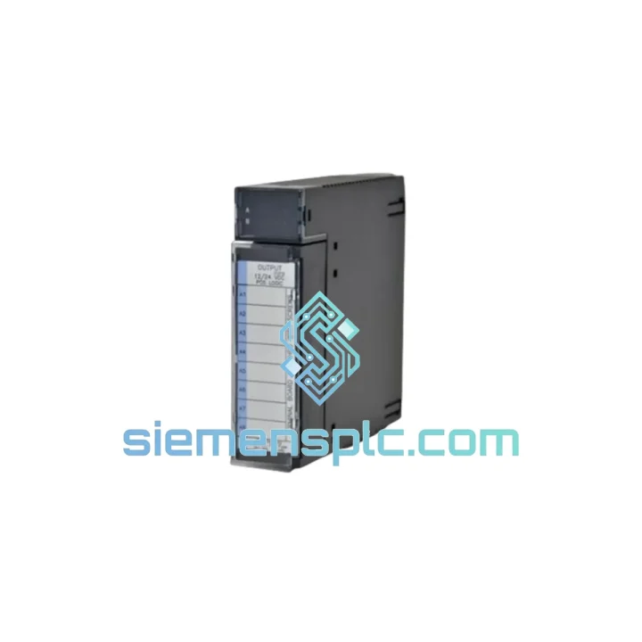
The GE IC693MDL730F is a single-slot, eight-channel positive-logic (high-side sourcing) discrete output module engineered for the GE Fanuc Series 90-30 programmable controller platform. Each channel switches a 12 VDC or 24 VDC field supply at up to 0.5 A continuous, with a module-level aggregate ceiling of 4.0 A. The “-F” suffix designates the terminal production revision of the IC693MDL730 lineage, incorporating refined terminal block latch geometry and tighter LED driver resistor tolerancing compared to revisions A through E, while preserving full electrical and mechanical backward compatibility across every Series 90-30 rack and CPU variant in the IC693 family.
In a Series 90-30 control architecture, the IC693MDL730F occupies the discrete output layer between the CPU’s resolved logic state and the physical field actuator. At the conclusion of each PLC scan cycle, the CPU writes an eight-bit output image register across the backplane bus to the module’s on-board latch. The module translates each bit state into a switched DC power path, energizing solenoid valves, relay coils, motor starter enable circuits, pilot lamps, and resistive or inductive DC loads within the 0.5 A per-channel envelope. The galvanic isolation barrier between the 5 VDC backplane domain and the 12/24 VDC field domain prevents field-side transients from propagating into the CPU bus and corrupting scan-cycle execution or analog reference planes shared by co-resident modules.
Real-time Stock & RFQ: [email protected] | WhatsApp: +86 18359268345
| Parameter | Specification |
|---|---|
| Part Number | IC693MDL730F |
| Manufacturer | GE Fanuc / GE Automation & Controls |
| Platform | Series 90-30 (IC693 family) — all CPU variants |
| Module Type | Discrete Output, Positive Logic (Sourcing / High-Side Switch) |
| Output Points | 8 independently controlled channels |
| Field Supply Voltage | 12 VDC / 24 VDC nominal |
| Output Current per Channel | 0.5 A continuous |
| Module Aggregate Current | 4.0 A maximum |
| Output Switch Topology | High-side MOSFET (sourcing — current flows module → load) |
| Field-to-Logic Isolation | Optical (photocoupler per channel group); 1,500 VAC rated |
| Backplane Power Draw | 5 VDC @ 250 mA typical |
| Inductive Load Suppression | Integrated flyback clamp diode per channel |
| Short-Circuit Protection | Electronic current limiting (load-side) |
| Status Indicators | 8 × individual green LED (gate-signal driven) |
| Field Wiring Interface | 20-pin removable keyed screw terminal block |
| Form Factor | Single-slot Series 90-30 I/O module |
| Operating Temperature | 0 °C to +60 °C |
| Storage Temperature | −40 °C to +85 °C |
| Relative Humidity | 5% to 95% RH, non-condensing |
| Pollution Degree | IEC 60664-1 Pollution Degree 2 |
| Certifications | UL Listed, cUL, CE Marked |
| Warranty | 12 months from date of shipment |
The IC693MDL730F implements a three-stage signal chain from backplane register to field terminal. The first stage is the backplane interface: during the output-update phase of the PLC scan, the CPU drives an eight-bit parallel word onto the Series 90-30 I/O bus. The module’s on-board ASIC latches this word synchronously with the backplane clock, holding the output state stable across the subsequent scan cycle regardless of concurrent bus activity from adjacent modules. This synchronous latch architecture eliminates glitch propagation — a property critical in applications where multiple output modules share a rack and simultaneous register writes could otherwise produce transient state changes on adjacent channels.
Photocoupler Isolation Stage: Each latched bit drives the anode of a dedicated photocoupler LED. The photocoupler’s collector-emitter output operates entirely within the 12/24 VDC field domain, providing a minimum 1,500 VAC galvanic isolation between the backplane 5 VDC logic rail and the field supply. This isolation rating exceeds the IEC 61131-2 requirement for Type 1 digital output modules in 24 VDC systems (500 VAC minimum) by a factor of three, providing substantial margin against field-side surge events. In mixed-signal racks where analog input modules such as the IC693ALG220 share the backplane, this barrier prevents common-mode noise injected by inductive field loads from coupling into the analog measurement ground reference — a failure mode that produces systematic offset errors in 4–20 mA current loop readings.
High-Side MOSFET Output Stage: The photocoupler output gates a discrete N-channel MOSFET configured in a high-side sourcing topology via a charge-pump gate driver. When the gate is driven high, the MOSFET connects the positive terminal of the 12/24 VDC field supply to the load terminal, sourcing current through the load to the common return. The MOSFET’s on-state resistance at 0.5 A produces a voltage drop of approximately 0.3–0.5 V, well within the tolerance of standard 24 VDC solenoid coils rated at ±10% supply variation. Electronic current limiting circuitry monitors the drain current and clamps it below the thermal runaway threshold under sustained short-circuit conditions, protecting both the module and field wiring without requiring individual fusing at each output terminal — though panel-level fusing per IEC 60204-1 remains recommended practice.
Inductive Kickback Suppression: Solenoid and relay coil de-energization generates reverse-EMF transients. Without suppression, a 24 VDC coil with 100 mH inductance switched at 0.5 A produces a flyback spike of several hundred volts in an unsuppressed circuit. The IC693MDL730F integrates a flyback clamp diode on each channel’s field-side output, clamping inductive kickback to approximately Vsupply + 1 V (≈25 V at 24 VDC supply). This eliminates the need for external MOV or RC snubber networks at each terminal, reducing field wiring complexity and removing a common source of long-term MOSFET gate oxide degradation from repetitive high-voltage transients.
LED Diagnostic Architecture: The eight status LEDs are driven from the MOSFET gate signal — not from the field load current path. This design decision has a specific diagnostic consequence: the LED state reflects the module’s commanded output state, independent of whether the field load is present or drawing current. A technician observing LED ON with no actuator response can immediately conclude the fault is field-side (open wiring, failed coil, blown fuse) rather than module-side, without connecting a programmer or multimeter. This distinction reduces diagnostic time in high-density panels where tracing individual field circuits is time-consuming.
Terminal Block Keying and Retention: The 20-pin removable terminal block uses a mechanical keying system that prevents insertion of a terminal block from a different IC693 module type. The latch mechanism on the F-revision incorporates a revised spring-steel retention clip requiring 15–20 N of deliberate extraction force, reducing the risk of accidental disconnection from vibration in mobile or transportation-mounted control panels. Field wiring remains attached to the terminal block during module replacement, allowing a module swap without disturbing wire terminations — a significant advantage in time-critical maintenance scenarios.
Every IC693MDL730F unit dispatched from our Xiamen, China facility undergoes a structured pre-shipment inspection protocol. Physical inspection covers PCB surface condition, solder joint integrity, terminal block latch function, label authenticity verified against GE Fanuc manufacturing documentation, and revision marking confirmation. Functional checks include power-on continuity verification and output channel actuation testing where test fixtures are available for the specific revision. Units are individually sealed in anti-static polyethylene bags, placed in foam-insert inner cartons dimensioned to prevent module movement during transit, and packed in double-wall corrugated outer cartons rated for international air freight handling per ISTA 2A test standards.
Air freight transit from Xiamen reaches major industrial procurement hubs on the following typical schedules: Southeast Asia 2–4 business days; Europe 5–7 business days; North America 5–8 business days; Middle East 4–6 business days; Australia 4–6 business days. Sea freight consolidation is available for bulk orders exceeding 20 units, with transit times quoted per destination port. Every shipment includes a commercial invoice, packing list, and certificate of conformance. Export classification and HS code documentation are prepared in-house and provided with each shipment to support customs clearance at the destination country.
A 12-month warranty from the date of shipment covers all units against manufacturing defects and functional failure under operating conditions defined in GE Fanuc IC693MDL730F product documentation. Warranty claims are processed within 5 business days of receipt of the returned unit at our Xiamen facility. Advance replacement arrangements are available for customers with established procurement relationships.
Email: [email protected]
WhatsApp: +86 18359268345
Web: siemensplc.com
Location: Xiamen, China
© 2026 siemensplc.com. All rights reserved.
We check the full part number, brand, series and visible nameplate information before quotation.
Sales confirms stock path, condition option, quantity and realistic lead time for export dispatch.
DHL, FedEx, UPS or buyer courier arrangements can be reviewed with packing requirements.
Similar brand or category products for fast comparison and multi-item RFQ lists.