GE
In Stock OK
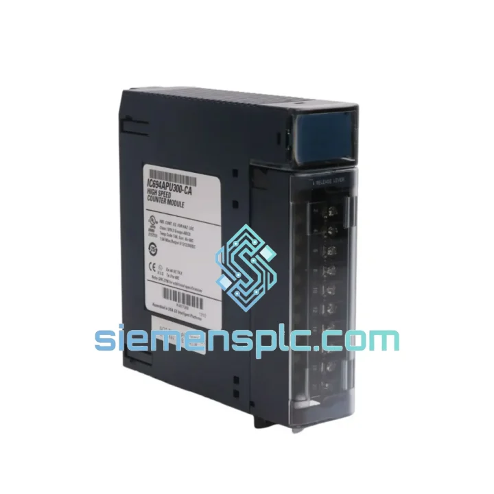
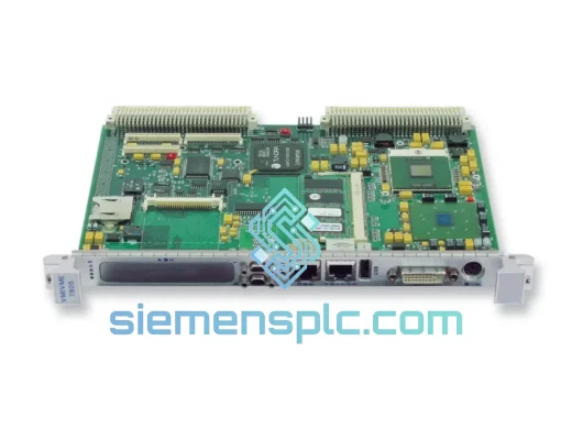
GE IC694APU300 PLC Module – Series 90-30
Request verified availability, condition, replacement risk review, packing options and courier lead time for IC694APU300.
BrandGE
Part NumberIC694APU300
ConditionAvailability Check
Lead TimeRFQ Confirmation
DocumentsDatasheet / photos by RFQ
ShippingExport packing available
Auto-filled RFQ
IC694APU300
Click Request Quote and the part number is inserted into the inquiry form automatically.
- Reply by email: [email protected]
- WhatsApp / Tel: +86 18359268345
- Mon-Sat 9:00-18:00 GMT+8
Procurement Data
Key Product Information
Core fields for model confirmation and RFQ routing. Detailed product narrative remains below.
- Brand
- GE
- Primary Part Number
- IC694APU300
- Product Type
- PLC Module
- Series / Family
- Fanuc
- Country of Origin
- US
- Catalog Category
- Robotics & Motion
- Operating Temp.
- 0°C to +60°C
- Warranty
- 12 months from date of shipment
Model confirmed for inquiry
IC694APU300
Send quantity, destination and urgency. The RFQ form keeps this part number attached.
Request Quote
Product Overview
GE IC694APU300: Dedicated High-Speed Pulse Counter for Series 90-30 Control Architecture
Within the Series 90-30 rack, the IC694APU300 Arithmetic Processing Unit occupies a single I/O slot and executes pulse accumulation, frequency measurement, and quadrature position tracking entirely in onboard hardware — decoupled from the CPU scan cycle. This architectural separation is the module’s defining characteristic: a 1 MHz encoder signal is captured and accumulated without any dependency on ladder logic execution time, eliminating the count-loss errors that occur when high-frequency inputs are handled by standard discrete input modules polled at scan rate.
The module accepts four independent counter channels, each with a dedicated 32-bit signed accumulator (range: ±2,147,483,647 counts), hardware preset and reset inputs, and a configurable output relay or transistor rated at 0.5 A. Each channel operates autonomously; a fault or overflow on channel 2 does not affect the accumulation state of channels 1, 3, or 4. This independence is critical in multi-axis conveyor indexing or multi-pump flow totalizing installations where simultaneous, uninterrupted counting across all channels is a process requirement.
Input conditioning supports both 5 VDC TTL-level signals (direct encoder interface) and 12–24 VDC sourcing/sinking field devices, with per-channel input current not exceeding 10 mA at 24 VDC. The differential input option provides common-mode noise rejection exceeding 1 kV/μs transient immunity per IEC 61000-4-4, which is the relevant standard for fast transient/burst immunity in industrial environments where VFD switching and arc welding generate broadband EMI across the 5–150 MHz spectrum.
Backplane communication uses the standard Series 90-30 parallel I/O bus. The CPU reads counter values from the %AI reference table and writes preset/control words to the %AQ table using the same mechanism as any analog I/O module. No special function blocks or motion libraries are required; the module is configured in Proficy Machine Edition (or Logicmaster 90-30) as an APU type in the hardware configuration table and is recognized natively by all IC693 and IC694 CPU variants from IC693CPU311 through IC694CPU780.
The IC694 mechanical revision (versus IC693APU300) uses an enhanced PCB substrate with improved conformal coating coverage on the counter ASIC and input conditioning circuitry, extending rated operating life in environments with cyclic humidity exposure. The backplane protocol and hardware configuration block are identical between IC693 and IC694 APU variants; no rack modification or CPU firmware update is required when substituting between them.
Real-time Stock & RFQ: [email protected] | WhatsApp: +86 18359268345
Technical Parameters
| Parameter | Value |
|---|---|
| Part Number | IC694APU300 |
| Platform | GE Fanuc Series 90-30 |
| Module Type | Arithmetic Processing Unit (APU) – High-Speed Counter |
| Counter Channels | 4 independent channels |
| Maximum Count Frequency | 1 MHz (single-ended); 250 kHz (quadrature A/B mode) |
| Accumulator Width | 32-bit signed integer per channel |
| Input Voltage | 5 VDC (TTL) / 12–24 VDC (sourcing or sinking) |
| Input Current | ≤ 10 mA per channel @ 24 VDC |
| Discrete Outputs | 4 outputs (relay or transistor), 0.5 A max each |
| Backplane Power Draw | 5 VDC @ 800 mA (typical) |
| Rack Slot Consumption | 1 slot (Series 90-30 standard) |
| Connector | 40-pin front-mount terminal block (IC693ACC301 compatible) |
| Operating Temperature | 0°C to +60°C |
| Storage Temperature | −40°C to +85°C |
| Relative Humidity | 5%–95% non-condensing |
| Vibration Rating | IEC 68-2-6, 5–150 Hz, 1 g |
| Shock Rating | IEC 68-2-27, 15 g, 11 ms half-sine |
| EMC Transient Immunity | IEC 61000-4-4, ≥1 kV/μs (differential input mode) |
| Certifications | UL 508, CE (EMC 2014/30/EU, LVD 2014/35/EU), CSA, RoHS |
| Weight | ~300 g |
| Warranty | 12 months from date of shipment |
Hardware Logical Analysis
Counter ASIC Architecture: The IC694APU300 implements counting logic in a dedicated gate-array ASIC rather than in firmware running on a shared microprocessor. This means the accumulator increment operation is a single clock-cycle combinational event — there is no interrupt latency, no context-switch overhead, and no shared bus arbitration delay between the field pulse edge and the register update. At 1 MHz input frequency, the inter-pulse interval is 1 µs; a firmware-based counter on a shared MCU with a 10–20 µs interrupt service routine would miss every pulse. The ASIC eliminates this constraint entirely.
Quadrature Decoding Logic: In A/B quadrature mode, the hardware decoder evaluates the phase relationship between the A and B encoder channels on each rising and falling edge of both signals, producing a 4× resolution multiplied count and a direction bit. This decoding is performed in combinational logic with propagation delay measured in nanoseconds, not in software with polling intervals measured in milliseconds. The Z (index) channel triggers a hardware latch that captures the accumulator value at the exact index pulse edge, providing a repeatable reference position without software intervention.
Optical Isolation on Input Stage: Each counter input channel passes through a high-speed optocoupler rated for signal frequencies up to 1 MHz. The optocoupler provides galvanic isolation between the field wiring (which may carry ground-loop potentials of several volts in large industrial installations) and the ASIC counting logic. The isolation barrier withstands 1,500 VAC continuous and 4,000 V surge, preventing ground-loop currents from corrupting the accumulator state or damaging the ASIC input stage.
EMC Design — Differential Input Path: The differential input configuration routes the encoder signal through a balanced line receiver (equivalent to RS-422 specification) before the optocoupler. Common-mode noise — the dominant interference mechanism in environments with large VFD installations — appears equally on both conductors and is rejected at the differential receiver with a common-mode rejection ratio (CMRR) exceeding 40 dB across the 1–10 MHz band. This rejection occurs before the signal reaches the optocoupler, preventing noise from modulating the LED drive current and generating phantom counts.
Backplane Register Map and CPU Handshake: The module presents its four 32-bit accumulators and status words as a contiguous block in the %AI reference table. The CPU reads this block during the input scan phase of each PLC scan cycle. Because the ASIC updates the backplane register asynchronously (every 1 ms hardware update interval), the CPU always reads the most recent completed count value without requiring a synchronization handshake. Preset and control words written by the CPU to the %AQ table are latched by the module at the next backplane output scan, providing deterministic control response within one scan cycle.
System Integration Benefits
- Scan-Independent Counting: Pulse accumulation continues uninterrupted during CPU program execution, I/O scan, and communication service phases. A 100 ms CPU scan cycle does not cause count loss at 1 MHz input frequency because the ASIC accumulates independently and the CPU reads the running total at each scan.
- Zero-Modification Retrofit: The module installs in any Series 90-30 baseplate slot (IC693CHS391/392/397, IC694CHS392/398) without rack modification, power supply upgrade, or CPU firmware update. Hardware configuration in Proficy Machine Edition requires only selecting the APU module type in the slot assignment table.
- Deterministic Preset Response: Hardware preset inputs latch the accumulator to a programmed value within one counter clock cycle (1 µs at 1 MHz), not within one CPU scan cycle. This enables position-reset operations synchronized to encoder index pulses with sub-microsecond repeatability.
- Diagnostic Transparency: The module reports channel overflow, underflow, and input signal loss as discrete status bits in the %AI data block. These bits are readable in standard ladder logic without special function blocks, enabling fault annunciation and safe-state logic within the existing program structure.
- Multi-Channel Independence: Each of the four channels maintains its own accumulator, preset register, and output control logic. A channel overflow or reset event on one channel does not affect the accumulation state of the remaining channels, which is essential in multi-pump or multi-conveyor installations.
- Reduced Slot Consumption: Four independent high-speed counter channels in a single rack slot versus four single-channel counter modules consuming four slots. In a 5-slot IC693CHS391 baseplate, this difference determines whether the application fits in one rack or requires an expansion rack with additional cabling and power supply cost.
- Broad CPU Compatibility: Compatible with IC693CPU311 through IC694CPU780 — the full production span of the Series 90-30 CPU family. A single spare module covers the entire installed base without version-specific stocking.
- Standard Programming Environment: No proprietary motion library or special instruction set is required. Counter values appear as standard %AI integers; control words are standard %AQ integers. Existing ladder logic programmers familiar with Series 90-30 I/O handling can integrate the module without additional training.
Quality Assurance & Global Logistics
Each IC694APU300 unit is sourced as genuine GE Fanuc original hardware — not rebranded, not refurbished without disclosure, and not of uncertain provenance. Before shipment from our Xiamen, China facility, every unit passes a documented four-stage inspection protocol:
Stage 1 — Physical Authentication: Housing, PCB markings, date codes, and connector pin condition examined against known-genuine reference units. Counterfeit indicators (inconsistent font, misaligned labels, incorrect PCB color) result in immediate rejection.
Stage 2 — Firmware Identification: Onboard firmware revision read and recorded. Revision is cross-referenced against GE Fanuc release documentation to confirm authenticity and identify any known firmware errata applicable to the customer’s CPU revision.
Stage 3 — Functional Bench Test: Module installed in a Series 90-30 test rack with IC694CPU364. All four counter channels exercised at 100 kHz, 500 kHz, and 1 MHz using a calibrated pulse generator. Quadrature mode tested with simulated A/B/Z encoder signals. Output relay and transistor operation verified under rated load. Pass/fail result recorded by serial number.
Stage 4 — Thermal Soak: 48-hour powered operation at 50°C ambient. Functional retest performed immediately after soak. Units that pass both pre- and post-soak tests are cleared for shipment. Test records are archived and available to the customer upon request.
Shipment from Xiamen, China to global destinations is executed via DHL Express, FedEx International Priority, or UPS Worldwide Express, with transit times of 3–5 business days to North America and Europe under standard conditions. Emergency shutdown orders can be processed for same-day dispatch when stock is confirmed before 14:00 CST. All shipments include a commercial invoice, packing list, certificate of conformance, and test report referenced to the unit serial number. Export documentation (ECCN classification, country of origin certificate) is prepared as standard for customs clearance.
The 12-month warranty covers defects in materials and workmanship under normal operating conditions as defined in GE Fanuc installation guidelines. Warranty claims are processed with a target replacement dispatch of 5 business days from confirmed fault diagnosis.
Contact Information
Email: [email protected]
WhatsApp: +86 18359268345
Web: siemensplc.com
Location: Xiamen, China
© 2026 siemensplc.com. All rights reserved.
Ready to quote
[email protected]
Send This Part Number to Sales
RFQ workflow
Quality workflow ->
Confirmation Process
01Model confirmation
We check the full part number, brand, series and visible nameplate information before quotation.
02Availability reply
Sales confirms stock path, condition option, quantity and realistic lead time for export dispatch.
03Packing & courier
DHL, FedEx, UPS or buyer courier arrangements can be reviewed with packing requirements.
Continue sourcing
Browse full catalog ->
Related Automation Parts
Similar brand or category products for fast comparison and multi-item RFQ lists.
GE
RFQ Ready
GE IC698RMX016-ED VMIVME-5567-100 Redundancy Module
Fanuc
Origin US
PLC Redundancy Module